SERVICE 7
13
19. Reinstall push rod and reattach push rods to con-
necting rods with wrist pin and bearings.
20. Replace all shields before operating unit.
7.7 HYDRAULIC HOSE REPLACEMENT
WARNING
DO NOT attempt to replace hydraulic hoses
while unit is in raised position. Hoses are under
extreme pressure. Releasing pressure improp-
erly could cause unit to drop rapidly.
Hydraulic fluid escaping under pressure can
have sufficient force to penetrate skin, causing
serious injury.
If a leak is suspected, use a piece of cardboard
or wood, not your hand, to check for leaks.
If injured by escaping fluid, see a doctor at
once. Serious infection or reaction can develop
if proper medical treatment is not administered
immediately.
Do not use a unit with a leaking hydraulic sys-
tem. See your authorized CUSHMAN dealer for
necessary repairs.
!
1. With engine stopped, move the Tines Control lever
to “Raise” for approximately 10 seconds. Then to
“Lower” for approximately 10 seconds. This releases
all pressure from the hydraulic hoses and cylinders.
2. Remove damaged hoses and install new ones using
pipe sealant on threads of each fitting.
3. Start engine and check for leaks while raising and
lowering the tines several times.
4. Check hydraulic fluid lever in reservoir, add if neces-
sary.
7.8 DOG CLUTCH ADJUSTMENT
(Refer to diagram, page 15.)
1. Raise unit, stop engine and block chassis to prevent
dropping.
2. Remove shields.
3. Disconnect connecting link (item 1 in diagram) from
transport clutch bell crank by removing clevis pin (5).
Remove rod connector link (3). Loosen connector
link (2) by backing both locknuts away from the
swivel pin.
4. Make sure clutches slide easily on shaft and engage
fully. If not, clean and lubricate shaft and clutch.
5. Tighten any play that may exist at joints where levers
clamp onto fork shafts.
6. Set Shift Control lever to “Neutral”. Hold or block the
lever so that it is tight against the top of its detent
hole.
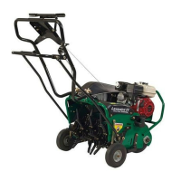
7. Move clutch lever (9) to attain a clearance of
.015”(.38mm) between the faces of the transport
clutch dogs. (See FIGURE 14.)
.015” (.38mm)
Sprocket
Dog Clutch
FIGURE 14
Transport Clutch Clearance (Neutral)
8. Tighten locknuts on connector link (2) against swivel
pin to maintain clearance.
9. Move shift control lever to “Aerate”.
10. Move lever (4) to fully engage aerate clutch with
.015”(.38mm) clearance. (See FIGURE 15.)
[Transport clutch should now be 1/16–3/32”
(1.5–2.5mm) from the edge of the drive shaft.]