9 ATTACHMENT
64
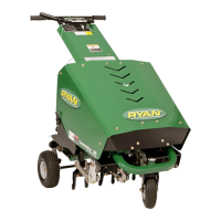
9.1 WINDROW ATTACHMENT
The windrow attachment is used to push the turf plugs
into a line that is out the way of the Greensaire wheel on
the succeeding pass.
9.2 INSTALLATION
1. Start the Greensaire and raise tines. Stop the
engine.
To prevent injury, block up the upper frame
when working on the unit with the tines raised.
Hydraulic lines may rupture, or lever could be
accidentally tripped, causing the unit to drop
rapidly.
WARNING
!
2. Locate and drill four 7/32″ (6mm) diameter holes
through rear door hinge plate and through plate to
which hinge is mounted. (See figure NO TAG for hole
locations)
FIGURE 1
1. Rear Door Hinge
2. New Hole Locations
3. Retain Hardware From
These Holes
3. Remove two screws and hardware indicated in fig-
ure NO TAG and retain to install deflectors.
4. Remove shield covering aerating frame.
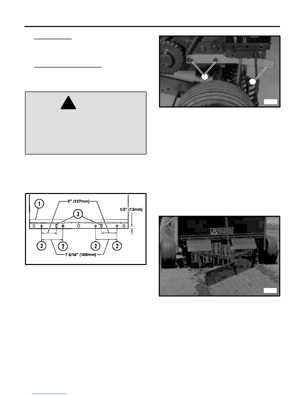
5. Remove two screws and oil seals from each end of
the camcase (location shown in figure NO TAG).
Install pivot arm to each side as shown in figure
NO TAG, using 1/2–13 x 1 screws with lockwashers.
Apply 3M Sealer #EC847 or equivalent to screws.
2
1
2287
FIGURE 2
1. Pivot Arm
2. Screw Locations
6. Attach windrow frame to outside of pivot arms with
5/16–18 x 1 1/4 screw, washer, bushing and locknut.
Be sure frame pivots at this connection.
7. Refer to the windrow parts drawing for the installa-
tion of the:
• Blade stop to frame
• Blade to yoke
• Yoke and chain tab to frame
8. Reinstall the shield covering the aerator frame and
install the chain bracket on top of the shield.
9. Install core deflectors using two sets of original hard-
ware and #10–24 x 1/2 flangelock screws and flan-
gelock nuts from kit. (See figure NO TAG)
1948
FIGURE 3
1. Deflectors Mounted To Door Hinge
10. Attach chain to chain tab with 5/16–18 x 7/8 screw,
washer and locknut. Hook the other end of the chain
to the slot in the chain bracket. When not in use raise
the windrow to the desired height and hook chain to
bracket.
11. Check crankcase oil level (in raised position) before
operating unit.