7 SERVICE
22
16. Install chain and wheels. Lower unit and replace all
shields before operating unit.
7.13 CAMSHAFT REMOVAL
WARNING
!
Lower unit to prevent it from dropping rapidly
during servicing.
1. Remove shields.
2. Drain oil from camcase. There are three drain plugs
in the camcase, open all three to be sure the three
sections of the camcase are drained.
3. Remove slides following steps 3 through 10 in the
“Slide Replacement” section on page 10.
4. On left side of unit, remove crankshaft and dog
clutch chains.
5. Loosen set screws in sprocket, and remove sprocket
and key from the camshaft.
6. On right side of unit, remove crankshaft and idler
chains.
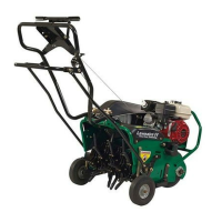
7. Remove cotter pin and washer from dog clutch link
and disengage link from dog clutch lever. Remove
dog clutch bracket from camcase. (See
FIGURE 37.)
3802
2
3
4
1
FIGURE 37
1. Dog Clutch Link
2. Dog Clutch Lever
3. Dog Clutch Bracket
4. Bearing Cage
8. Remove snap ring holding sprockets. Slide sprock-
ets off shaft and remove key.
9. Remove bearing cage and shims bolted to camcase.
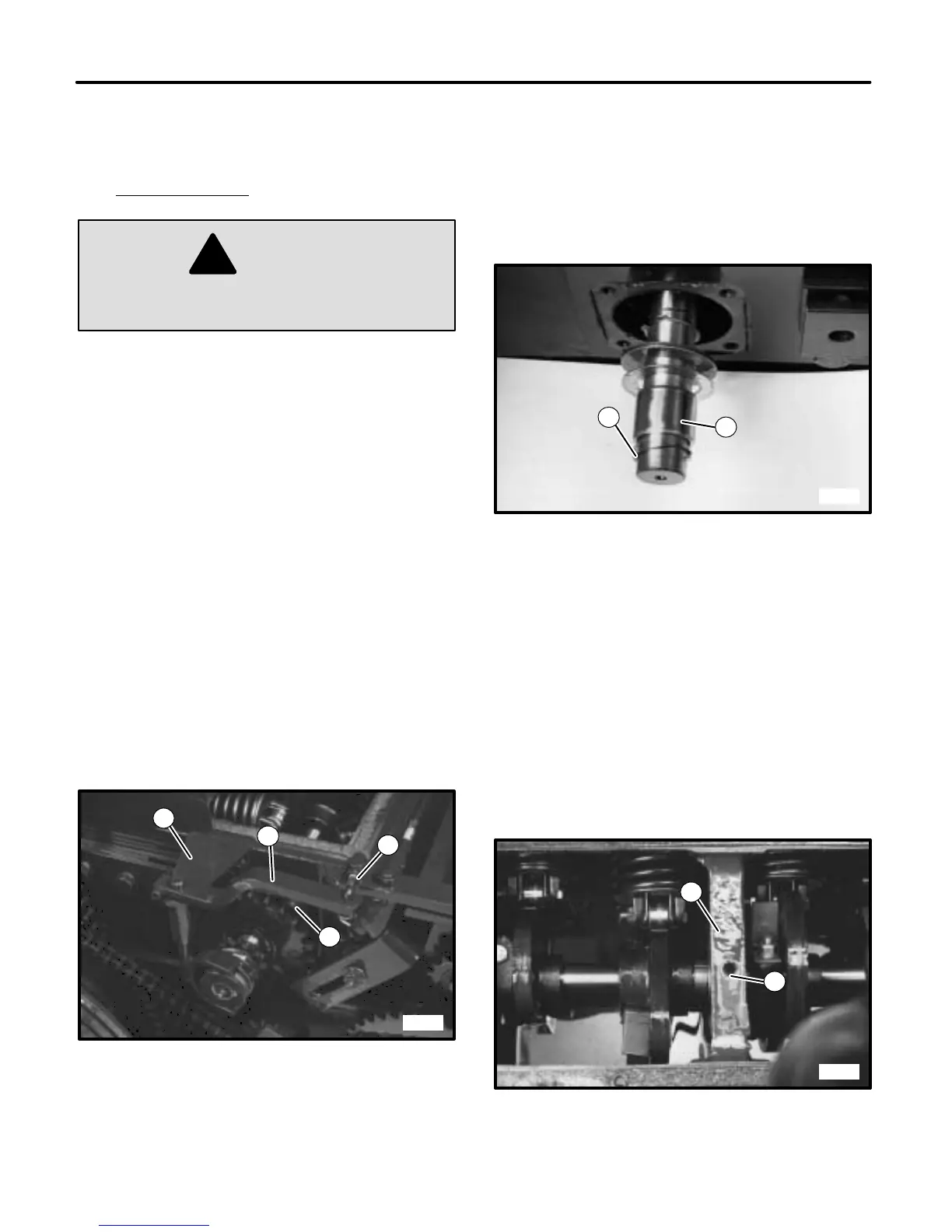
10. Remove spiral lock ring and slide washer, bearing
and bearing race off camshaft. Remove remaining
washers and inner snap ring. (See FIGURE 38.)
3803
1
2
FIGURE 38
1. Spiral Lock Ring
2. Bearing Race
11. Loosen cams. Slide cams along shaft to allow
access to keys. Remove keys by tapping down one
end with a punch. Key will swivel out of keyway.
12. Remove bearing cage and shims from left side of unit
and start to slide camshaft out from left side.
Remove cams and spacers from shaft while sliding it
out of camcase. Once removed, the left side bear-
ings and washers can be removed.
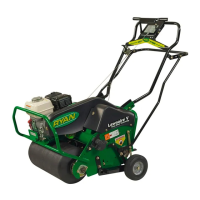
13. If the center bearings need to be removed, loosen
set screws (in camcase webbing) and tap bearings
from case. (See FIGURE 39.)
3788
1
2
FIGURE 39
1. Camcase Webbing
2. Set Screw