Introduction Page 2
Document id: 7000 108-011 A2
CONTENTS
I COPYRIGHT I
II SAFETY INSTRUCTIONS I
1 INTRODUCTION 4
1.1 About this manual 4
1.2 Unpacking the equipment 4
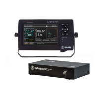
1.3 System overview 5
2 MOUNTING 5
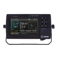
2.1 R4 Display Unit 6
2.1.1 Location 6
2.1.2 Clearance area 6
2.1.3 Physical mounting measurements 6
2.1.4 Cabling 6
2.1.5 Power Supply 6
2.2 R4 Transponder Unit 7
2.2.1 Location 7
2.2.2 Clearance area 7
2.2.3 Physical mounting measurements 7
2.2.4 Cabling 7
2.2.5 Power Supply 7
2.2.6 Transponder status LED:s 8
2.3 AIS Alarm Unit 9
2.4 Pilot Plug 10
2.5 VHF antenna 11
2.5.1 Antenna location 11
2.5.2 Antenna type 11
2.5.3 Antenna separation 11
2.5.4 Clear view of the horizon 12
2.5.5 Antenna height 12
2.5.6 Cabling 12
2.5.7 Cable mounting 12
2.5.8 Grounding 12
2.6 GPS antenna 12
2.6.1 Antenna location 13
2.6.2 Cabling 13
2.6.3 Cable mounting 13
2.6.4 Grounding 14
2.7 Wiring Input/Output connections 15
2.7.1 R4 Display cable connections 15
2.7.2 R4 Transponder cable connections 16
2.8 System configuration and settings 18
2.8.1 R4 Display Keys 18
2.8.2 System Power Up 19
2.8.3 Engineering Mode 20
2.8.4 MMSI , IMO number, Call Sign, Ships Name, Height Over Keel 20
2.8.5 GPS antenna position 22