4.5
HYBRID SOLAR INVERTER INSTRUCTION MANUAL
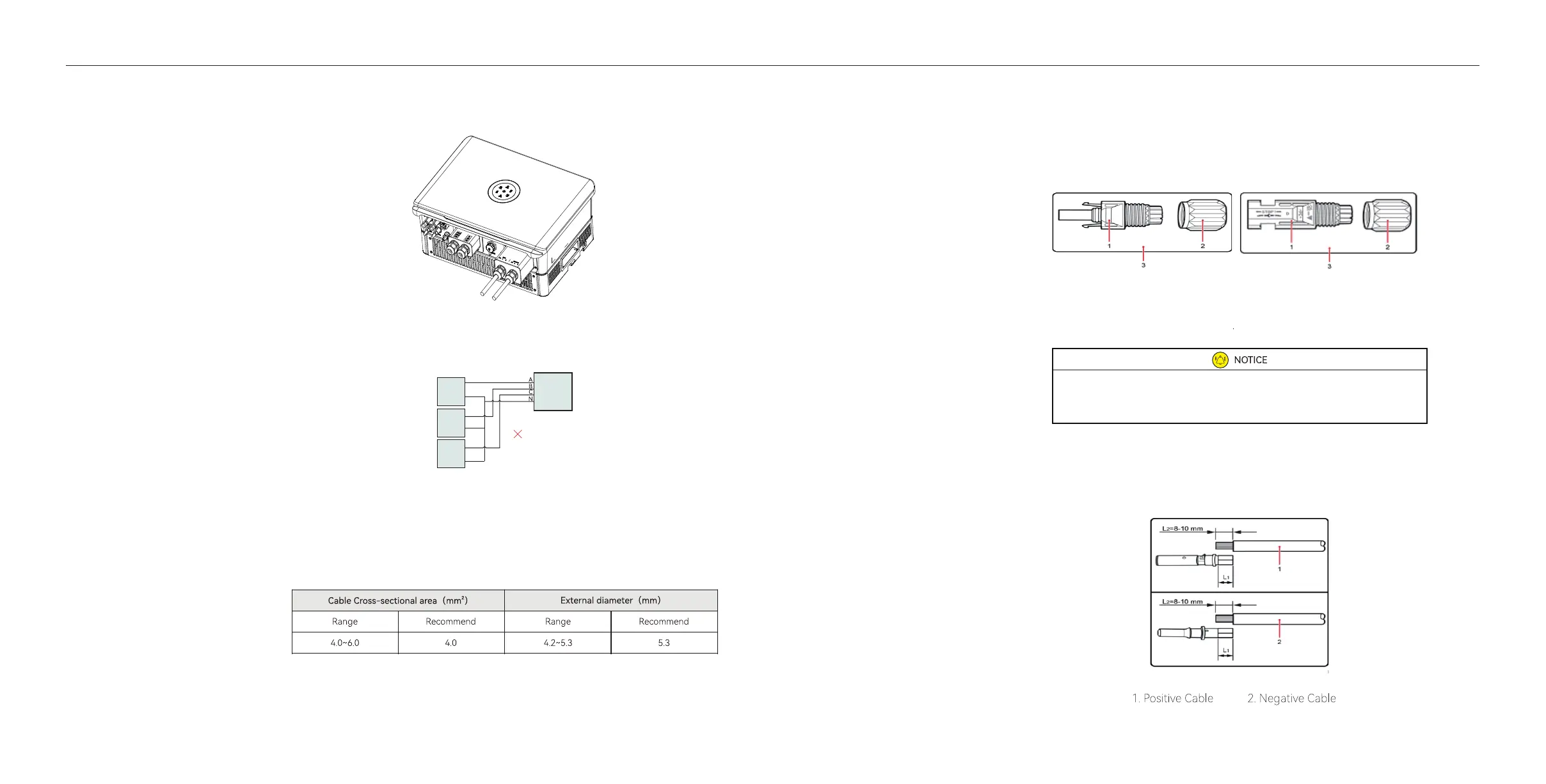
PV Connection
4.During o grid operation time, PE line at the BACK-UP end will remain to be connected with
the PE line at the power grid end inside the inveer. (Only applicable to market in Australia)
3.Secure all pas of the grid and backup connector tightly.
Figure 4.5
Screw the Connector
Table 4.3
Recommended
Specications of DC Cables
Figure4.7
Positive and negative connectors
Figure4.8
Connecting Cables
DC connector is made up of the positive connector and the negative con-
nector
Connecting Procedures:
1. Use specied strip tool to strip the insulated enclosure of the positive
and negative cables with appropriate length (8-10mm).
·Please place the connector separately after unpacking in order to avoid confusion for connection of cables.
·Please connect the positive connector to the positive side of the solar panels, and connect the negative connector
to the negative side of the solar side. Be sure to connect them in right position.
20
19
4.4.1
Multiple Inveer
Combinations
Inveer
1 Phase
Test Circuit
Connection
3 Phase
Inveer
1 Phase
Inveer
1 Phase
The inveer should not be installed in multiple phase combinations.
1. Insulated Enclosure 2. Lock Screw3. Positive/ Negative Connector

 Loading...