T-Max® Manager/Plus and T-Max®3A/F/I User’s Guide Page 46
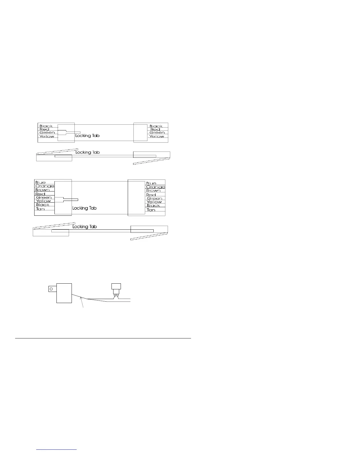
12.11 Figure K - Modular Cable Pinouts
RJ-22 Connector Untwisted Modular Cable RJ-22 Connector
Use this diagram if you are making your own cables
Important!!!
Salon Systems, Inc. highly recommends that you do not modify the cables provided with each T-Max®3A/F/I. If you need
longer cables, contact your dealer or Salon Systems, Inc. All cables are pre-tested at the factory for proper connection. If
you are not careful in making your own cables, the system may not work properly!
12.12 Figure L - Example Of An External Push Button Circuit
The T-Max®3A/F/I can be ordered with an external push button option. When 5 or 12Volts is applied to the External Start
input on the T-Max®3A/F/I while it is in Delay, the bed will be energized with out having to press the Start/Stop button.
Above is an example of an push button circuit.
To Ext. Start on
T-Max®3A/F/I
5 or 24VAC Out
External Push Button
120VAC
RJ-45 Connector Untwisted Modular Cable RJ-45