EB 8384-4 EN 9
Design and principle of operation
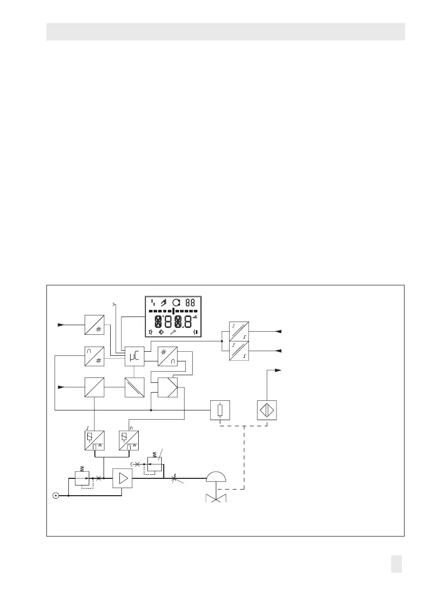
3 Design and principle of oper-
ation
The positioner is mounted on pneumatic con-
trol valves and is used to assign the valve
position (controlled variablex) to the control
signal (set pointw). The positioner compares
the control signal of a control system to the
travel or rotational angle of the control valve
and issues a signal pressure (output vari-
abley) for the pneumatic actuator.
The positioner mainly consists of an electric
travel sensor system, an analog i/p convert-
er with a downstream air capacity booster
and the electronics with the microcontroller.
When a system deviation occurs, the actua-
tor is either vented or lled with air. If neces-
sary, the signal pressure change can be
slowed down by a volume restriction. The
signal pressure supplied to the actuator can
be limited by software or on site to 1.4, 2.4
or 3.7bar.
The xed ow regulator ensures a constant
air ow to the atmosphere, which is used to
ush the inside of the positioner housing and
to optimize the air capacity booster. The i/p
converter is supplied with a constant up-
stream pressure by the pressure regulator to
compensate for any uctuations in the supply
pressure.
1 Control valve
2 Travel sensor
3 PD controller
4 A/D converter
5 Microcontroller
6 i/p converter
7 Air capacity booster
8 Pressure regulators
9 Flow regulator
10 Volume restriction
11*
Inductive limit switch
12*
Solenoid valve
13 IEC61158-2 interface
module
14 Binary input BI1
(voltage input)
15*
Binary input BI2
(for oating contact)
16 Display
17*
Actuation of solenoid valve
18 Electrical insulation
19 D/A converter
20 Serial interface
* Options
w
x
Q
%
S
mm
GG
PD
Serial
Interface
16
15
11
2
4
13
20
17 18
19
24V DC
5
3
12
6
7
8
10
1
14
9
x
y
Fig.1: Functional diagram

 Loading...


