EB 2512 EN 3-1
Design and principle of operation
3 Design and principle of oper-
ation
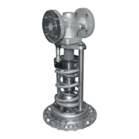
Î RefertoFig.3-1
The Type 41-23 Pressure Reducing Valve
consistsofaType2412ClosingValveanda
Type2413Actuator.Thevalveandactuator
(exceptfortestedregulators)aredelivered
separately and must be assembled together
according to these instructions (see the 'In-
stallation' section).
The pressure reducing valve is used to main-
tain the pressure downstream of the valve to
an adjusted set point.
Theprocessmediumowsthroughthevalve
between seat (2) and plug (3) in the direc-
tion indicated by the arrow on the body. The
position of the valve plug determines the
owrateand,asaresult,thepressureratio
across the valve. The plug stem is sealed by
a frictionless bellows (5.1). The downstream
pressure p
2
is transmitted over the compen-
sation chamber (18) (for liquids above
150°Candforsteam)andthecontrolline
(17) to the operating diaphragm (12) (oper-
ating bellows (12.1) in the version with bel-
lows actuator) where it is converted into a
positioning force. This force is used to move
the valve plug depending on the force of the
set point springs (7). The spring force is ad-
justable at the set point adjuster (6). The
valves with K
VS
4andhigherhaveabalanc-
ing bellows (4). The upstream pressure acts
on the outside of the bellows and the down-
stream pressure on the inside of the bellows.
As a result, the forces produced by the up-
stream and downstream pressures acting on
the plug are balanced out.
Depending on the valve and actuator used,
the regulator can be upgraded to create a
pressurereducingvalveforlowowrates,a
steam pressure reducing valve or a pressure
reducing valve with increased safety (actua-
tor with two diaphragms).
The valve closes when the downstream pres-
sure rises.
LegendforFig.3-1
1
Valve body
2
Seat
3
Plug
4
Balancingbellows
5
Plug stem
5.1
Bellows
6
Set point adjuster
7
Set point springs
7.1
Spring plate
8
Crossbeam
8.1
Pillar(viewdrawnturnedby90°)
8.2
Nuts for pillars
8.3
Tapped holes
9
Fastening nuts
10
Diaphragmactuator/bellowsactuator
11
Actuator stem
12
Operating diaphragm
12.1
Operating bellows
13
Diaphragm plate
14
Diaphragm plate nut
15
Nuts and bolts
16
ControllineconnectionG¼
(with screw joint with restriction when used
with steam)
17
Control line (to be provided on site)
(available as control line kit for direct
pressure tapping at the body uT2595)
18
Compensation chamber
19
Filler plug
20
Travel stop cap with cotter pin