EB 2512 EN 3-3
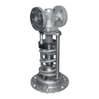
Design and principle of operation
3.1 Additionalttings
Î RefertoFig.3-2
Strainers
We recommend installing a SAMSON
strainer (2) upstream of the valve. It prevents
solid particles in the process medium from
damaging the regulator.
Î Do not use the strainer to permanently
ltertheprocessmedium.
Î Selectastrainer(meshsize)suitablefor
the process medium.
Any impurities carried along by the process
medium may impair the proper functioning
of the regulator. We recommend installing a
strainer (e.g. SAMSON Type2NI) upstream
of the pressure reducing valve (uEB1015).
Pressure gauges
Install a pressure gauge (3 and 5) both up-
stream and downstream of the regulator to
monitor the pressures prevailing in the plant.
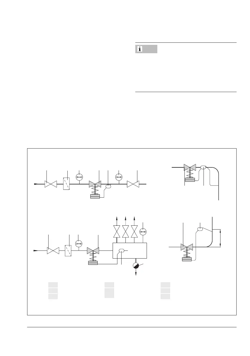
Note
Control line connection in pipeline:
Controllineconnectionbelowthe
middleoftheange:
184
Min. pipe diameter ½“
Control line connection in manifold: Connectionabovethemiddleoftheange:
1 2
4
18
3
H
k
H
k
= Additional condensate head
1
Shut-off valve
2
Strainer
3
Upstream pressure gauge
4
Pressure reducing valve
5
Downstream pressure
gauge
6
Shut-off valve
7
Steam trap
18
Compensation chamber
Fig.3-2: Sample application