9-6 EB 2512 EN
Servicing
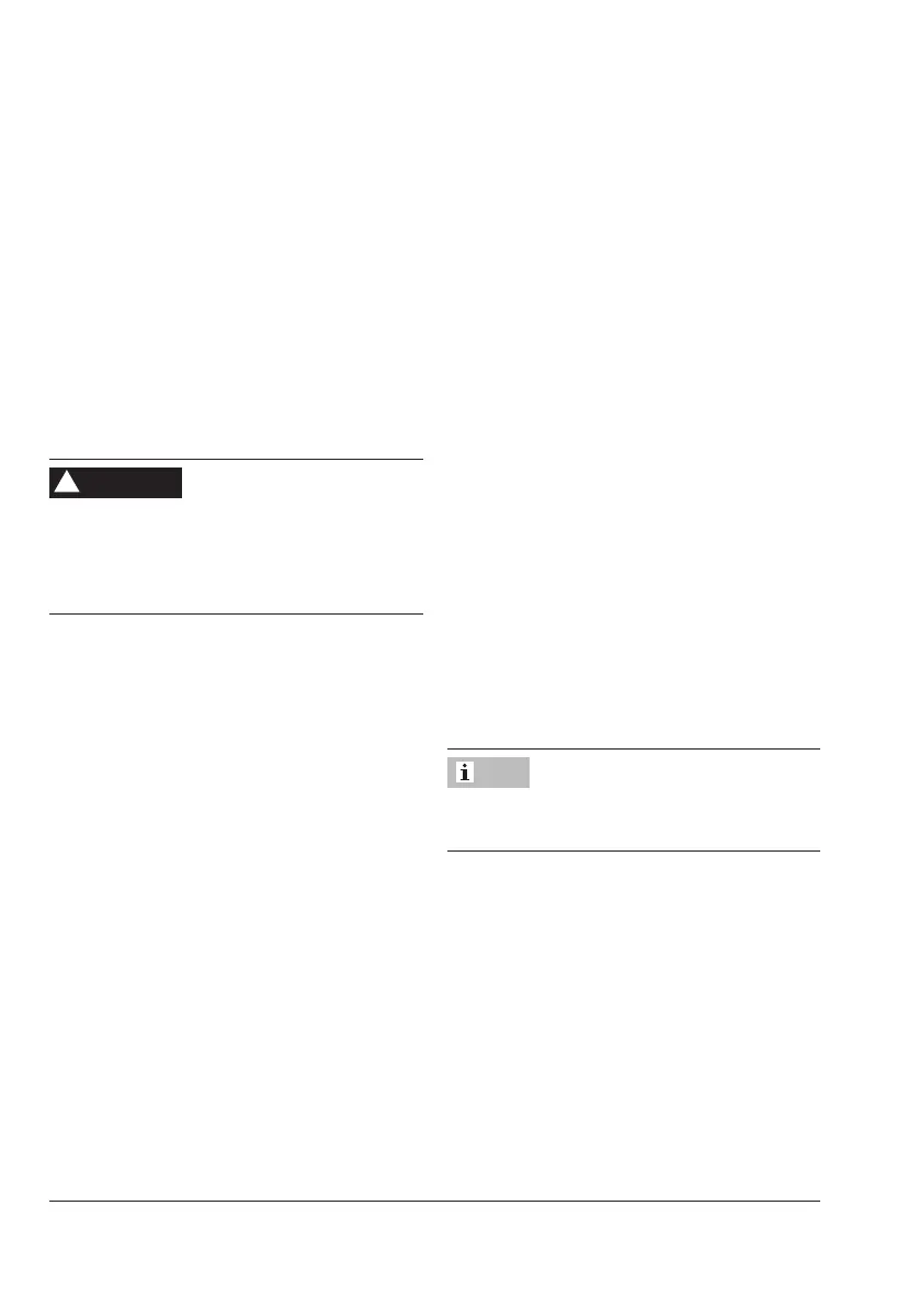
9.3.2 Replacing the set point
springs
Î RefertoFig.9-1
Removing the set point springs
1. Put the regulator out of operation (see
the 'Decommissioning' section).
2. Completely relieve the tension from the
set point springs (7) by turning the set
point adjuster (6) counterclockwise ().
Stored energy in the set point springs can
cause components to move in an uncon-
trolled manner resulting in injury to hands or
ngers.
3. Unscrew the control line (17).
4. Remove the device from the pipeline
5. Unlock the cotter pin (20) on the travel
stop cap.
6. Remove the actuator (10) from the valve
(seesection9.3.1).
7. Unscrew the nuts (8.2) on the crossbeam.
Remove the crossbeam (8).
8. Remove the travel stop cap with cotter
pin (20) and spring plate (7.1).
9. Lift off the set point springs (7).
WARNING
!
WARNING
!
Mounting the set point springs
1. Place the set point springs (7) on the set
point adjuster (6).
2. Place on the spring plate (7.1) and the
travel stop cap with cotter pin (20).
Place the crossbeam (8) on the pillars
(8.1) and fasten with the nuts (8.2). Ob-
servethetighteningtorquesspeciedin
thetheAnnex.
3. Mount the actuator (10) (see sec-
tion9.3.1).Observethetightening
torquesspeciedinthetheAnnex.
4. Lock the cotter pin (20) on the travel stop
cap.
5. Install the regulator into the pipeline.
6. Screw on the control line (17). Observe
thetighteningtorquesspeciedinthethe
Annex.
7. Put the regulator into operation (see the
'Operation' section).
Change the nameplate and conguration ID
after changing the set point range.
Note