5-6 EB 2512 EN
Installation
5.3 Assembly
Tested SAMSON regulators are delivered as
an assembled unit. In all other cases, the
separate components (valve, actuator and
control line) of the regulator are delivered
separately. Upon delivery, the separate com-
ponents must be assembled together. Pro-
ceed as follows to assemble the regulator
and to prepare for start-up.
Risk of regulator damage due to exces-
sively high or low tightening torques.
Observe the specied torques on tightening
regulator components. Excessively tightened
torques lead to parts wearing out quicker.
Parts that are too loose may cause leakage.
Î Observe the specied tightening torques
(see Annex).
Risk of regulator damage due to the use of
unsuitable tools.
Î Only use tools approved by SAMSON
(see Annex).
Risk of regulator damage due to the use of
unsuitable lubricants.
Î Only use lubricants approved by
SAMSON (see Annex).
NOTICE
!
NOTICE
!
NOTICE
!
5.3.1 Installing the regulator
1. Close the shut-off valves upstream and
downstream of the regulator while the
regulator is being installed.
2. Remove the protective caps from the
valve ports before installing the valve.
3. Lift the valve using suitable lifting equip-
ment to the site of installation. Observe
theowdirectionthroughthevalve.The
arrow on the valve indicates the direction
ofow.
4. Makesurethatthecorrectangegaskets
are used.
5. Boltthepipetothevalvefreeofstress.
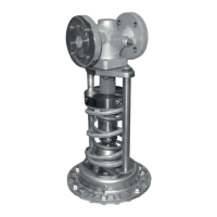
6. Mount the actuator.
Î DiaphragmactuatorDN15to100
− Insert the actuator stem (11) through the
hole in the crossbeam (8) into the travel
stop cap with cotter pin (20) and fasten
the actuator with the nuts (9). Observe
thetighteningtorquesspeciedinthe
Annex.
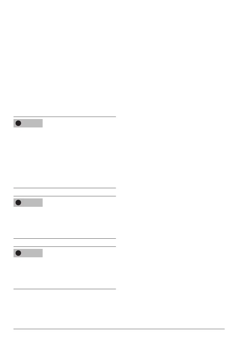
Î BellowsactuatorDN15to50
− Remove the crossbeam (8) from the
valve.
− Insert the actuator stem (11) into the trav-
el stop cap with cotter pin (20).
− Align pillars (8.1) and fasten the actua-
tor with the nuts (8.2). Observe the tight-
eningtorquesspeciedintheAnnex.