EB 2512 EN 5-5
Installation
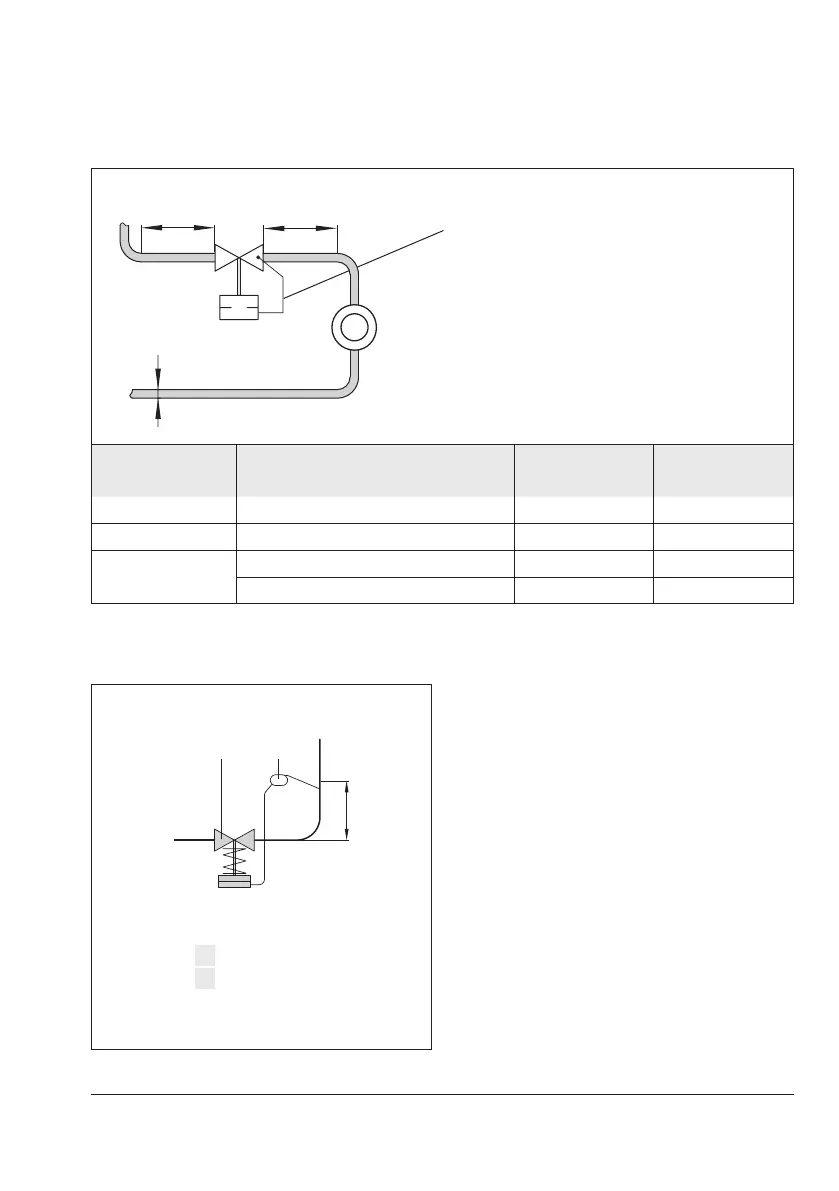
Table5-6: Inlet and outlet lengths
Control line (e.g. control line kit, see
information under ‘Control line’)
DN
a x DN
b x DN
a Inlet length
b Outlet length
State of process
medium
Valve conditions Inlet length a Outlet length b
Gas Ma≤0.3 2 4
Vapors
1)
Ma≤0.3 2 4
Liquid
Freeofcavitation/w<3
m
/
s
2 4
Cavitationproducingnoise/w≤3
m
/
s
2 4
1)
No saturated steam
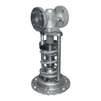
Connectionabovethemiddleoftheange:
H
k
Additional condensate head
4 Pressure reducing valve
18 Compensation chamber
Fig.5-3: Example of installation with steam