5-2 EB 2512 EN
Installation
Support or suspension
The plant engineering company is responsi-
ble for selecting and implementing a suitable
support or suspension of the installed regula-
tor and the pipeline.
Depending on the regulator version and
mounting position, the valve, actuator and
pipeline must be supported or suspended.
Do not attach supports directly to the valve
or actuator.
Control line
The control line must be provided at the site
of installation, e.g. a
3
/
8
“ pipe for steam or
an8x1or6x1mmpipeforair/water.
Connect the control line to the downstream
line (p
2
) at least one meter away from the
valve outlet.
Weld the control line at the side in the mid-
dle of the pipe, inclining at a ratio of ap-
proximately1:10uptothecompensation
chamber. If a manifold is located down-
stream of the pressure reducing valve, con-
nect the valve to the manifold, even if it is
severalmetersaway(seeTable5-6and
Fig.5-2).
Control line kit
A control line kit for tapping pressure at the
valve body is available as an accessory part
from SAMSON.
Note
NOTICE
!
Do not install any instruments (e.g. tempera-
ture regulators or shut-off valves) that restrict
the cross-section of the pipe between the
pressure tapping point and the regulator.
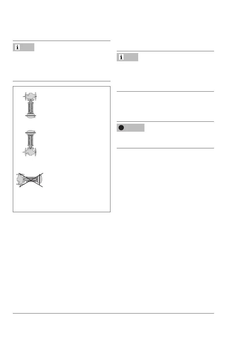
Standard mounting position
For gases, liquids and steam
Alternative mounting position
for gases and liquids at medi-
um temperature upto80°C.
Not for steam.
Not permissible!
1)
Fig.5-1: Mounting position
1)
On request: Permissible for regulators with
xedplugstemguidepluswithmedium
temperatureupto80°C.Notforsteam.
Note