EB 2512 EN 5-3
Installation
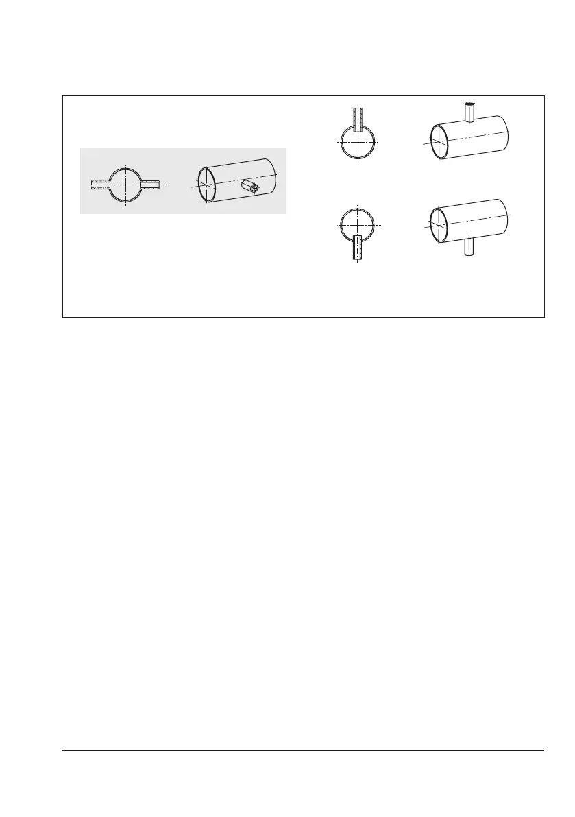
Correct!
Incorrect!
Connection at the top – incorrect position
Incorrect!
Connection at the side – optimal Connection at the bottom – incorrect position
Fig.5-2: Control line connection, depending on how the pipeline is routed
If the control line connection is located below
themiddleofthevalveinletange,arrange
the compensation chamber at the same level
astheinletange.Inthiscase,useapipe
whichisatleast½“insizeforthecontrol
line from the tapping point to the compensa-
tion chamber.
If the control line is connected above the
middleofthevalveinletange,installthe
compensation chamber at the same level as
the upstream pressure tapping point. The ad-
ditional pressure of the condensate head (H
k
,
Fig.5-3)mustbecompensatedforbyadjust-
ing the set point.
Needle valve
If the regulator tends to hunt, we recommend
installing a needle valve at the control line
connection (16) in addition to the standard
SAMSON screw joint with restriction.
Compensation chamber
A compensation chamber (18) is required
forliquidsabove150°Caswellasfor
steam. The mounting position of the compen-
sation chamber is indicated by an adhesive
label on the chamber itself as well as by an
arrow and the word "top" stamped on the
top of the chamber.
Thismountingpositionmustbeadheredto;
otherwise the safe functioning of the regula-
tor cannot be guaranteed.
Weld the line coming from the pressure tap-
ping point to the
3
/
8
“ pipe socket on the
chamber.
Install the compensation chamber at the
highest point of the pipeline. Consequently,
the control line between compensation
chamber and actuator must also be installed
with a downward slope. In this case, use a
3
/
8
“pipewithscrewttings.