EB 2512 EN 9-5
Servicing
Mounting the actuator
1. DiaphragmactuatorDN15to100
Insert the actuator stem (11) through the
hole in the crossbeam (8) into the travel
stop cap with cotter pin (20) and fasten
the actuator with the nuts (9). Observe
thetighteningtorquesspeciedinthethe
Annex.
− BellowsactuatorDN15to50
Insert the actuator stem (11) into the trav-
el stop cap with cotter pin (20).
Align actuator on the pillars (8.1) and
fasten it with the nuts (8.2). Observe the
tighteningtorquesspeciedinthethe
Annex.
− BellowsactuatorDN65to100
Screw the pillars (8.1) into the threaded
holes(8.3)oftheactuatorangeasfar
as they will go.
Insert the actuator stem (11) into the trav-
el stop cap with cotter pin (20).
Fasten the pillars (8.1) with the nuts (8.2)
ontothevalveange.Observethetight-
eningtorquesspeciedinthetheAnnex.
2. Lock the cotter pin (20) on the travel stop
cap.
3. Screw on the control line (17). Observe
thetighteningtorquesspeciedinthethe
Annex.
4. Put the regulator into operation (see the
'Operation' section).
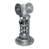
9.3.1 Replacing the actuator
Î RefertoFig.9-1
Removing the actuator
1. Put the regulator out of operation (see
the 'Decommissioning' section).
2. Unscrew the control line (17).
3. Completely relieve the tension from the
set point springs (7) by turning the set
point adjuster (6) counterclockwise ().
Stored energy in the set point springs can
cause components to move in an uncon-
trolled manner resulting in injury to hands or
ngers.
4. Unlock the cotter pin (20) on the travel
stop cap.
5. DiaphragmactuatorDN15to100
Unscrew the nuts (9) from the actuator
and remove the actuator.
− BellowsactuatorDN15to50
Unscrew the nuts (8.2) from the actuator
and remove the actuator.
− BellowsactuatorDN65to100
Unscrew the nuts (8.2) on the pillars
(8.1).
Unscrew the pillars (8.1) out of the
threaded holes (8.3) of the actuator
angeandremovetheactuator.
WARNING
!
WARNING
!