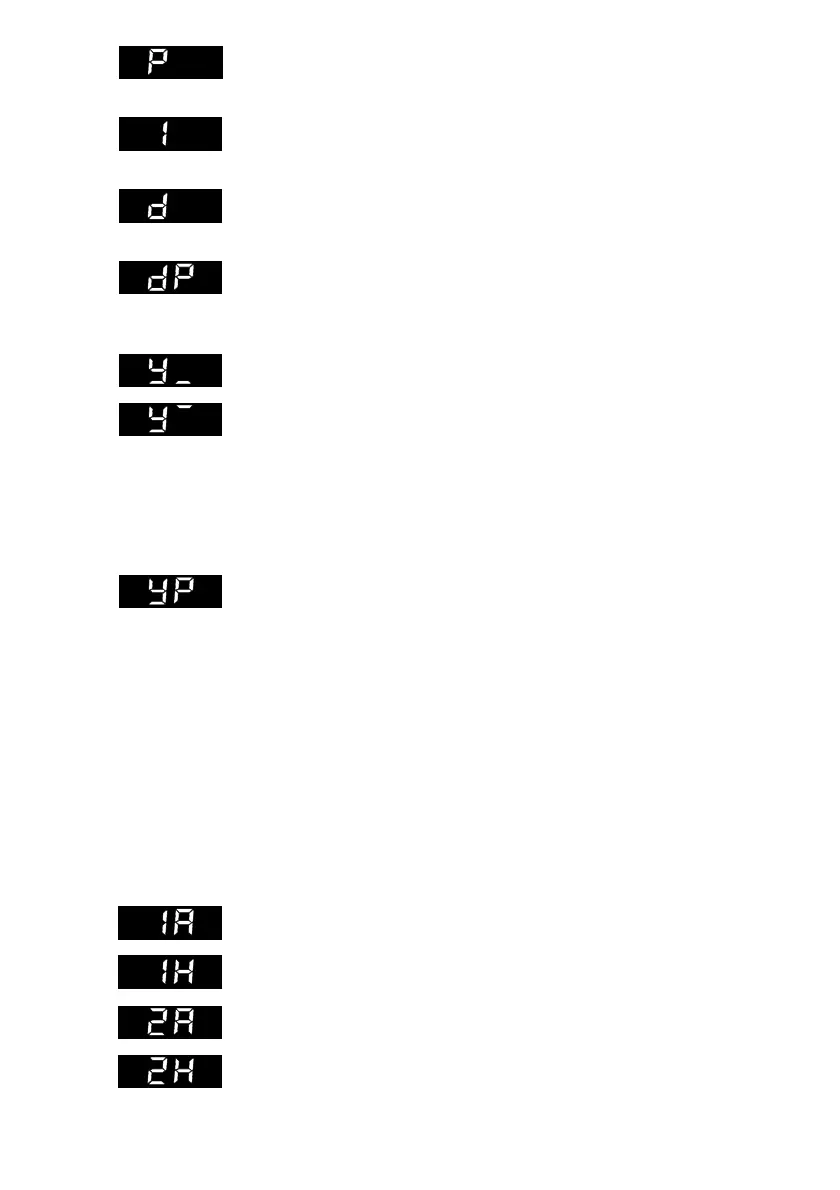
Proportional-action coefficient
P (Kp)
,
P
-action component of the controller
Range of values 0.1 to 100.0
Integral-action (reset) time I (Tn)
,
I
-action component of the controller
Range of values 0 to 2000 s,
disabled when set to
0
Derivative-action (rate) time D (Tv)
,
D
-action component of the controller
Range of values 0 to 2000 s,
disabled when set to
0
Derivative-action (rate) gain
dP
, gain of the D-action component
Range of values 0.0 to 10.0 (D-action component only enabled when a
value >0 is specified for
dP
.
Output variable limits
Y__
= –110.0 % to Y
—
Y
—
= Y__ to +110.0 %
This limit is
ineffective
for MANUAL function.
Selection of the output variable range determines the lower-limit (start) and
upper-limit (end) value of the output signal range. The numeric values are
displayed as percents of the selected controller output range.
Example:
Y0
= 0, current range 0 to 20 mA
Y__
= 20 %, Y
—
= 80 % → controller output Y = 4 to 16 mA
Working point
YP
(only active if I-action component = 0)
The setting range of working point
YP
corresponds to the setting range for
output variable Y.
To set working point
YP
, the current value of the output variable display must
be read when the plant is in the steady-state and set as value for the working
point. Thus, the offset (steady-state deviation) of a P or PD controller is elimi-
nated when the setpoint is fixed-set.
The limit value and the differential gap for switching outputs
Y1
and
Y2
are defined with the dis-
plays shown below:
Selection
of the limit value and the alarm condition is set in the configuration level via configura-
tion block
Y1
or
Y2
.
Further explanations on the switching outputs can be found in chapter 5.
For
Y
=
0
or
2
Limit value
Y1
For
Y
=
0
or
2
Differential gap for
Y1
For
Y
=
0
or
2
Limit value for
Y2
For
Y
=
0
or
2
Differential gap for
Y2
15