5.2.2 Assignment of the limit alarm conditions for switching outputs
Y1
and
Y2
Limit alarm contact
Y1
is assigned in configuration block
Y1
.
Y2
is assigned with configuration
block
Y2
. The default configuration does not assign an alarm condition to the limit alarm con-
tacts (configuration switches
Y1
=
0
and
Y2
=
0
).
Only the assignment options for limit alarm contact
Y1
are described in the following section.
Note that limit alarm contact
Y2
functions in the same way as that of contact
Y1
. Input variable
X
can be monitored to determine if a limit value is fallen short of (
Y1
=
1
) or exceeded (
Y1
=
2
).
There is also the possibility of monitoring controlled deviation
XD
. In this case, it is possible to
monitor the controlled deviation to determine if it is fallen short of (configuration switch
Y1
=
3
)
or exceeded (configuration switch
Y1
=
4
).
When
XD
is monitored with configuration switch
Y1
=
5
, the value can be evaluated to identify
whether or not XD has been exceeded.
Likewise, controller output Y can be monitored to determine if it has fallen short of (
Y1
=
6
) or
exceeded (
Y1
=
7
). The method of monitoring output signal Y is described in the next section.
5.2.3 Monitor output signal
Y
Output signal Y can be monitored to determine if it the limit value is exceeded in either direction.
Apart from the pure two-output used to determine if a limit value is exceeded in either direction,
a three-step action can be implemented when configuration blocks
Y1
and
Y2
are appropri-
ately set.
With the combination
Y1
=
6
and
Y2
=
7
or
Y1
=
7
and
Y2
=
6
, a three-step switching output is
implemented which uses fixed switching points. No internal feedback is applied in this case.
In this type of configuration, either a P or PD algorithm (set
P
,
d
,
dP
) is recommended. Working
point
YP
should be set, and the output variable limit
Y__
should be set to –100.0 %.
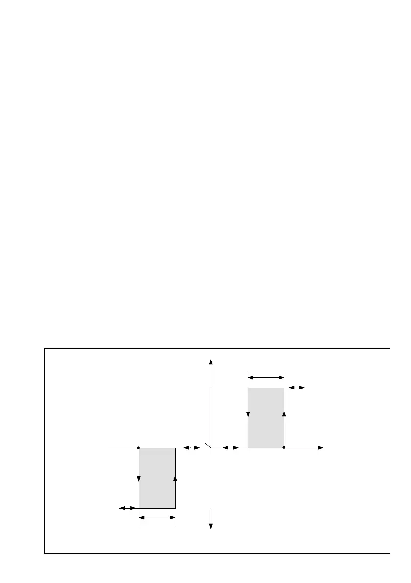
Fig. 11 ⋅ Switching 2*on-off output with Y1 = 7 and Y2 = 6
2A
1A + Y (%)
Y1
Y2
1H
2H
Off
On
On
27