5.2.4 Pulse-modulated on-off controller output at switching output
Y1
and/or
Y2
The pulse-modulated controller output is a switching output in which the output signal is a pulse
frequency. In this case, the pulse-pause ratio is varied for a specified period of time (
t1
). Here,
the period is entered in seconds with parameter
t1
. The minimum on-time is set as a percentage
using parameter
td
.
Selection of the pulse-modulated switching output is made in configuration block
Y1
=
8/9
and/or
Y2
=
8/9
.
Y1
=
8
selects a clocked controller output in a positive direction of output sig-
nal Y. When configuration switch
Y1
=
9
, a clocked control controller output
Y1
is selected in a
negative direction of output signal Y. Switching output
Y2
operates similarly, with
Y2
=
8
or
9
.
The switching action operates the same as an on-off controller output with internal feedback.
5.2.5 On-off pulse-modulated controller output with limit alarm
In this type of output circuit, a switching output (
Y1
or
Y2
) is pulse modulated in either a positive
output signal direction (
Y1
or
Y2
=
8
) or negative output signal direction (
Y1
or
Y2
=
9
). In this
case, the period of time
t1
and the minimum pulse duration
td
is set for the pulse-modulated
controller in the parameterization level.
The other switching output is activated upon an alarm condition. The limit alarm condition is set
with configuration switch
Y1
=
1
to
7
(controller output
Y1
) or
Y2
=
1
to
7
(controller output
Y2
).
This limit condition refers to the parameter
1A
(
for
Y1
) or
2A
(
for
Y2
) set in the parameterization
level. In addition, the differential gap must be set with parameter
1H
(controller output
Y1
) or
2H
(controller output
Y2
).
5.2.6 Two pulse-modulated on-off switching outputs
In order to achieve two pulse-modulated controller outputs which are effective with positive
and/or negative output signals Y, configuration switch
Y1
=
8/9
and
Y2
=
8/9
must be set. In
this case, the period of time
t1
and the minimum pulse duration
td
are simultaneously set for
both pulse-modulated controller outputs.
Example:
Configuration switch
Y1
=
8
sets the pulse-modulated two-point switching output which is set by
positive output signal Y. Configuration switch
Y2
=
9
sets a pulse-modulated switching output for
negative output signals Y.
Pulse-modulated on-off controller outputs are suitable to control heating — cooling applica-
tions.
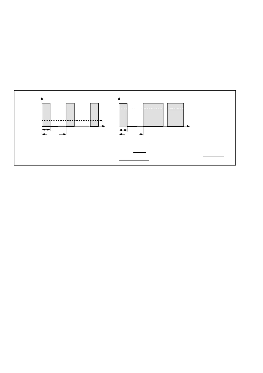
Fig. 12 Clocked controller output
t1 = 100 s
t1 = 100 s
Y=75 %
t
t
Y1
Y2
tmin
tmin
Y=25 %
On
Off
On
Off
Example:
Period t1 = 100 s
Min. puls time td = 5 %
This corresponds to: tmin =
5 %
⋅
100 s
100 %
= 5 s
tmin =
td
⋅
t1
100
%
28