5.1 Three-step controller with internal feedback (
Y
=
1
)
The three-step controller incorporating internal feedback is selected in the configuration level
with configuration switch
Y
=
1
.
In this configuration scheme, switching output
Y1
is then active when the difference between the
calculated
Y
PID
signal and the internal feedback is positive. Switching output
Y2
is always active
when this difference is negative.
With dead band
td
, a range (neutral zone) can be defined in which the switching signal is still
not to be active.
Dead band
td
applies in equal proportions for positive and negative output signals (50% each).
The hysteresis which can be commonly set for both switching points is set as a percentage using
parameter
tH
.
Example:
Y
PID
= 20 %;
YR
= 16 %;
Y
=
Y
PID
–
YR
= 20 % – 16 % =
4 %
.
In a situation where the set dead band
td
= 10 %,
Y1
is not active. Reason: 5 % dead band for
positive output signals is not exceeded. If differential gap
tH
is set with 1 %, then
Y1
is only active
when
Y
> 5 %.
Y1
is then disabled whenever
Y
< 4 %.
The internal feedback is to be adapted, in seconds, to the installed actuator using parameter
t1
(motor operating time). The internal feedback simulates the behaviour of the installed actuator.
By inserting an internal feedback, the discontinuous-action controller output takes on a beha-
viour resembling that of a continuous controller output (quasi-continuous controller output).
t1
= Operating time of the implemented actuator (in seconds)
td
= Dead band as a percentage
tH
= Hysteresis as a percentage
For the selection of three-step controller providing internal feedback (
Y
=
1
), configuration
blocks
Y1
and
Y2
are insignificant and cannot be altered.
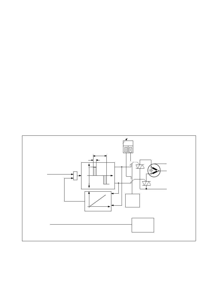
+
_
Y
R
Y
t1
Y
R
Y1
Y2
%
tH
td
L1
PE
N
Y1
Y2
PID
Manual
(from continuous-action
controller section)
Comparator
Internal feedback Motor operating time t1
MANUAL/
AUTOMATIC
key
X-Recorder
0(4) to 20 mA
X-Value for recorder input
Fig. 9 ⋅ Three-step switching
25