3. Electrical connections
The easy-to-install compact controller is equipped with plug-type connectors (snap-in contacts)
for lead sizes 0.3 to 0.8 mm
2
and an insulating diameter of 1.3 to 2.4 mm
2
or screw terminals
for lines 0.5 to 1.5 mm
2
. When connecting the electric leads, note the pertinent VDE 0100 regu-
lations and the currently valid regulations mandated by the country where the controller is in-
tended for use.
Wiring information
The signal and sensor leads are to be isolated from those of the controller and power supply.
To avoid measuring errors when radio interference is present, use shielded lines for signals and
sensors.
The power supply lines of each controller are to be led separately to the corresponding distribut-
ing bus bar.
Suppress contactor circuits located in the vicinity against interference using an RC element.
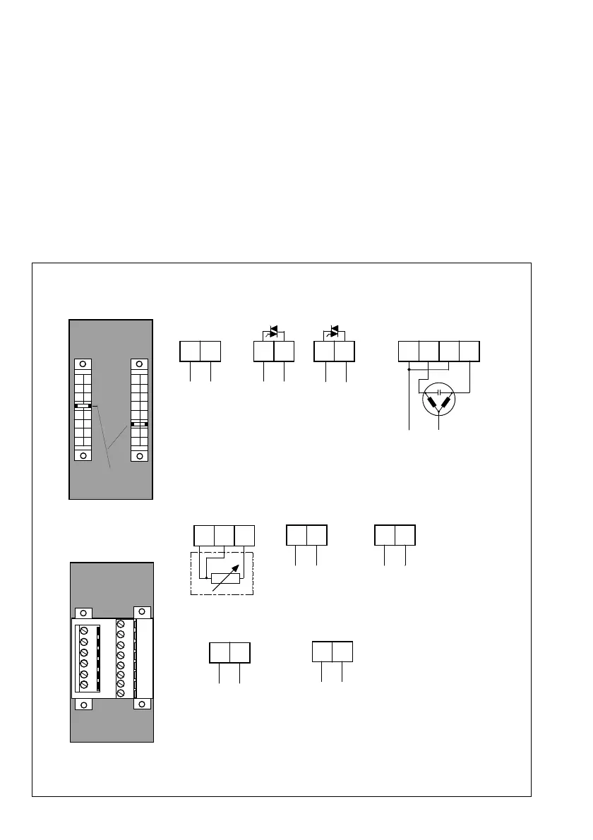
Fig. 4 ⋅ Terminal assignment
1
C
L
N
5
F
7
H
5
F7
H
+
_
Y1
Y2
L
N
+
_
5
E
D
C4C
3
+
-
+
-
2B
+
-
mA
V
A
B
C
D
E
G
H
1
2
3
4
5
7
8
X1
X2
H7F5C1
X1
X2
mA
A1
+
-
51E423C/D A/B
A
B
C
E
F
G
H
1
2
3
5
6
7
8
Snap-in Contacts
Screw terminals
Code
Back
Back
Power supply
100 to 253 V a.c.
or 24 V a.c./d.c.
2 x limit contacts (TRIAC)
Three-step switching output
for a current >0.5 A requires
contactors or relays
Note:
Y1 or Y2 can only be operated with
a.c. voltage. Note correct phase
connection of power supply.
Pt 100/Ni 100
4(0) to 20 mA
2(0) to 10 V
Terminals X2
Controller input (controlled variable x)
Binary input BE
0/24 V
Controller output (output signal y)
(continuous) 4(0) to 20 mA
Note:
When using a three-step switching output or limit contacts,
the continuous controller output is available as analog output
for controlled variable x.
Terminals X1
8