SAMWONTECH
2nd Edition of TEMP2000_Series IM : July. 16. 2010 Page 37 / 87
4.2 Retransmission Output Setup
4.2.1 Output Setup Screen-2
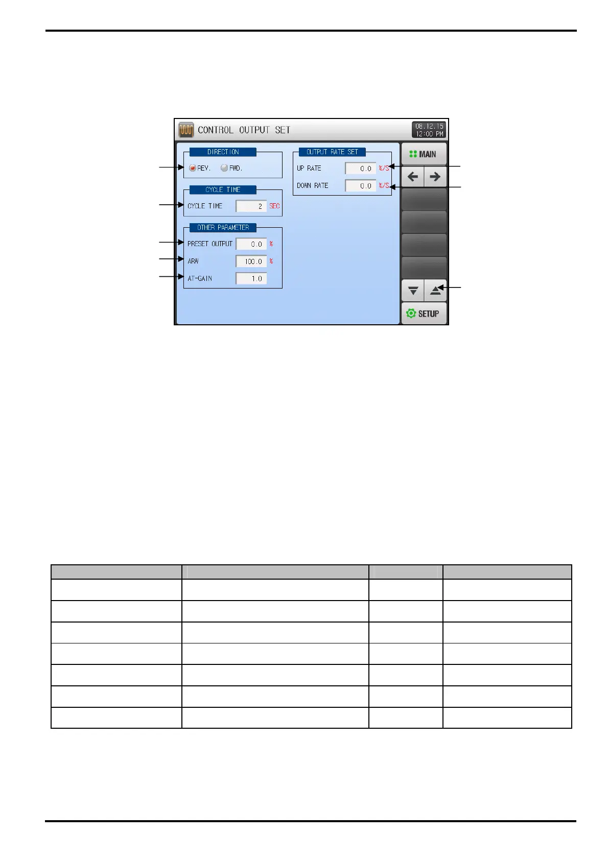
① Set PID control operation method.
☞ Refer to [4.2.1.1 Operation Direction]
② Set Cycle Time for control output operation when control output is “SSR(SOLID STATE RELAY)”.
③ Send preset Emergency Output after cutoff the PID output when STOP, S.OPN occurs.
④ Set Over-Integral Prevention Rate(Value) when over-integral prevention function is in operation.
☞ Refer to [4.2.1.3 Over-Integral Prevention]
⑤ Used to manual adjust the all PID value according to system characteristic after Auto Tuning.
☞ Control Output = PID X Control Constant (GAIN)
☞ Refer to [4.2.1.4 Control Constant]
⑥ Set upward change rate of output when control output increases.
⑦ Set downward change rate of output when control output decreases.
⑧ Move to previous or next screen using Up/Down button.
Table 4-2 Output Setup Screen-2 Parameter
Parameter Range Unit Default
Operation Direction Reverse / Forward ABS Reverse
Output Cycle 1~300 SEC ABS 2
Emergency Output -5.0~105.0% % 0.0
Over-Integral Prevention 0.0(AUTO), 0.0 ~ 200.0% % 100.0
Control Constant 0.1~10.0 ABS 1.0
Upward Change Rate 0.0(OFF) ~ 100.0 %/Sec %/Sec 0.0(OFF)
Downward Change Rate 0.0(OFF) ~ 100.0 %/Sec %/Sec 0.0(OFF)
①
②
③
⑤
④
[Figure 4-4] Output Setup Screen-2
⑥
⑦
⑧