SAMWONTECH
2nd Edition of TEMP2000_Series IM : July. 16. 2010 Page 71 / 87
11. DIGITAL INPUT (DI) CONFIGURATION
11.1 DI Operation Setting
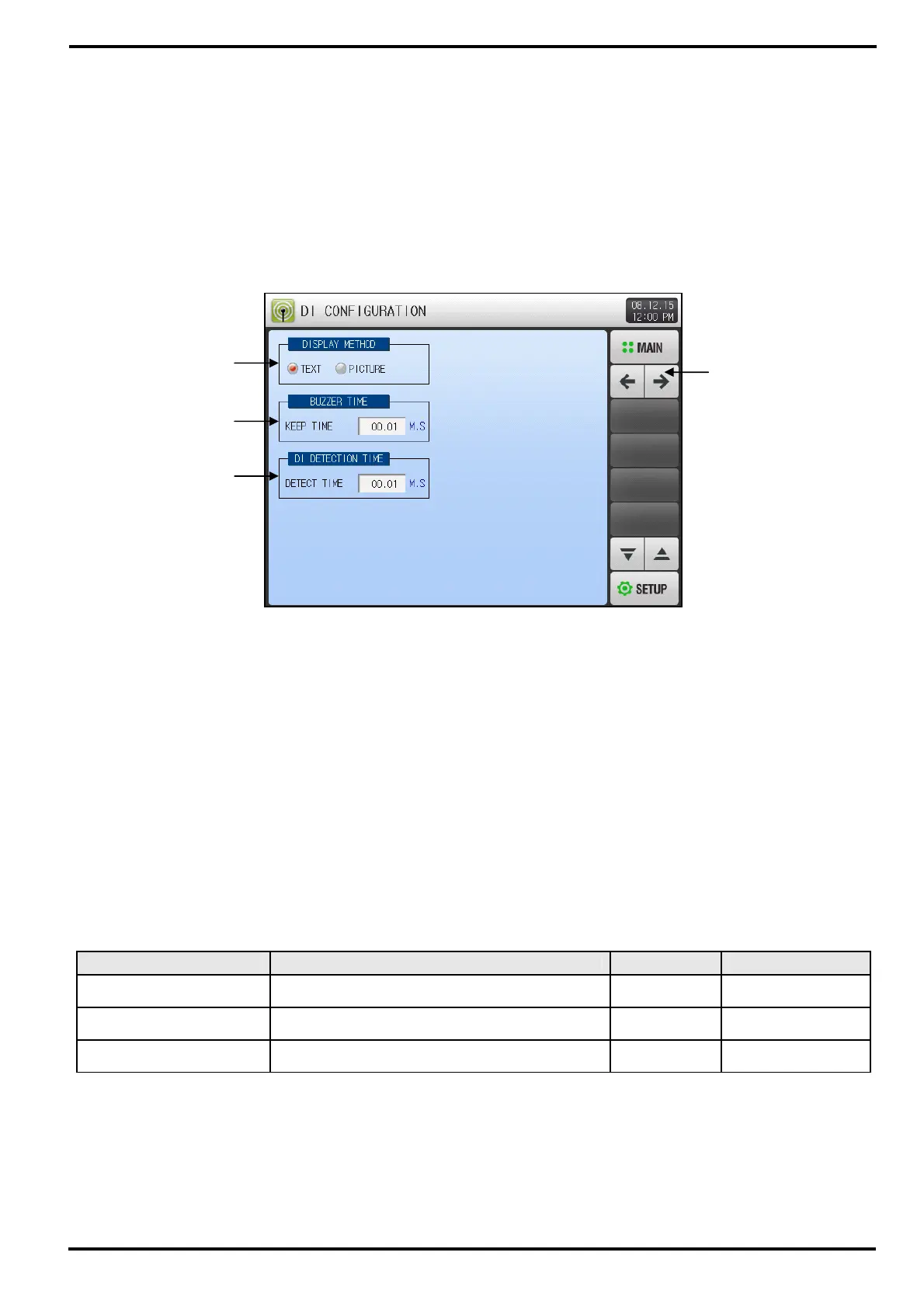
11.1.1 DI Function and Operation Screen-1
▶ Display Method of ‘Picture’ can only be selected when SD CARD option is selected.
☞ Refer to [2.11 User Menu]
① Set DI Display Mode when error occurs.
☞ Text : Refer to [Figure 11-11 Text Type DI Error Display Screen]
☞ Picture : Refer to [Figure 11-12 Picture Type DI Error Display Screen]
- DI Error Picture is displayed only when there is Figure File(BMP) at internal memory.
② Set Buzzer duration time when DI error is occurred.
☞ The Buzzer will sound even though it is set to “0” when DI error is occurred.
☞ Buzzer will not sound when DI 1, 2, 3 operation type is set to Run/Stop, Hold and Step.
But Buzzer will sound when it is set to Error.
③ Set DI Detection Delay Time.
☞ When physical DI contact occurred, if contact is ON for setup time, it regards as DI Input.
④ Move screen to previous or next.
Table 11-1 DI Function and Operation Setup Screen-1 Parameter
Parameter Range Unit Default
Display Method Text, Picture ABS Text
Buzzer Time 0.00 ~ 99.59 (MIN.SEC) ABS 00.01
DI Detection Time 0.00 ~ 99.59 (MIN.SEC) ABS 00.01
①
②
③
④
[Figure 11-1] DI Function and Operation Setup Screen-1