PDG-DSU30 Condential 2-5
A
B
D
EF
C
Item
Male Connector
on Main Board
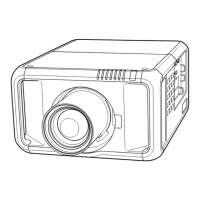
The key feature Figure
A Lamp Driver Black wire tube (5 pin)
B Fan
Compose of Red/Yellow/Black
Wire (3 pin)
C Blower
Compose of Red/Black/White
Wire, white connector and Black
wire tube (3 pin)
D Photo Sensor
Compose of Red/Black/White
Wire, red connector and Black
wire tube (3 pin)
E IR
Compose of Red/Black/White
Wire, green connector and Black
wire tube (3 pin)
F Speaker
Compose of Red/Black Wire and
Black wire tube (2 pin)
2-8 Disassemble Main Board
Module
1. Unscrew 3 screws (as red circle).
2. Unplug the connector (as green square)
of Color Wheel.
3. Unplug 6 connectors (as orange square).
Please refer to the table as below for
details of each connector.
 Loading...