-34-
Electrical Adjustments
1. Enter the service mode.
2. Receive the 16-step grey scale composite video sig-
nal with Video mode.
3. To start the auto-calibration for Component adjust-
ment, select group no. “260”, item no. “0” and then
change data value from “0” to “1”. After the auto-cali-
bration completed, "OK" will appear on the screen.
6. Auto Calibration adjustment [Video]
Gain adjustment [Video]
1. Enter the service mode.
2. Receive the 16-step grey scale composite video signal
with Video mode.
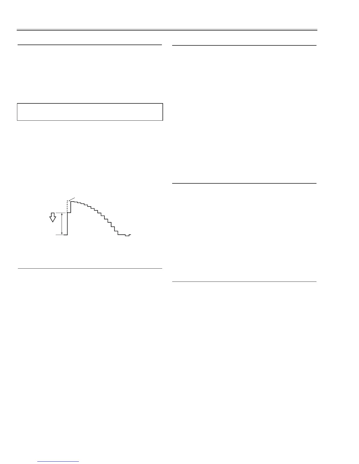
3. Connect an oscilloscope to test point “TP35G” (+)
and chassis ground (-).
4. Select group no. “20”, item no. “0” and adjust the
amplitude “a” to be minimum by changing the Data
value.
below adjustment is performed when the above auto
calibration is failed.
1. Enter the service mode.
2. Receive the 50%-Whole Gray computer signal with
Computer1 [RGB] mode.
3. Select group no. “ 100”, item no. “ 92” and change
data value to “ 2” to reduce the panel frequency.
4. Project only green light component to the screen.
5. Select group no. “ 101”, item no. “ 1” and change
data value to obtain the minimum flicker on the
screen.
6. Project only red light component to the screen.
7. Select item no. “ 0” and change data value to obtain
the minimum flicker on the screen.
8. Project only blue light component to the screen.
9. Select item no. “ 2 and change data value to obtain
the minimum flicker on the screen.
10. Select group no. “ 100”, item no. “ 92” and change
data value to “ 0” to reset the panel frequency.
7. Common Center adjustment
Equipment Luminance meter
Input mode Video (Video)
Input signal 100%-white and 50%-gray
composite video signal
1. Enter the service mode.
2. Input the 100%-white composite video signal and
measure luminance on the screen with the
luminance meter. It is
A
for the reading of luminance
meter.
3. Change the signal source to the 50%-white
composite video signal.
4. Select group no. “
100
”, item no. “
6
” and change the
Data value to make the reading of luminance meter
to be
A x 22%.
10. 50% White adjustment [Video]
1. Enter the service mode,
2. Receive the 16-step gray scale computer signal with
Computer1 [RGB] mode.
3. Select group no. “100” item no. “7” (Red) or “8”
(Blue), and change Data values respectively to make
a proper white balance.
Confirm that the same white balance is obtained in vid-
eo and computer input.
9. White Balance adjustment [PC]
Equipment Luminance meter
Input mode Computer 1 (RGB)
Input signal 100%-white and 50%-gray computer
signal
1. Enter the service mode.
2. Input the 100%-white computer signal and measure
luminance on the screen with the luminance meter.
It is
A
for the reading of luminance meter.
3. Change the signal source to the 50%-white
computer signal.
4. Select group no. “
100
”, item no. “
6
” and change the
Data value to make the reading of luminance meter
to be
A x 22%.
8. 50% White adjustment [PC]
 Loading...