7. EXPLANATION OF PARAMETERS
7-43
Mode Page
Abbre-
viation
Name and description
Standard
value
Unit
Setting
range
Remarks
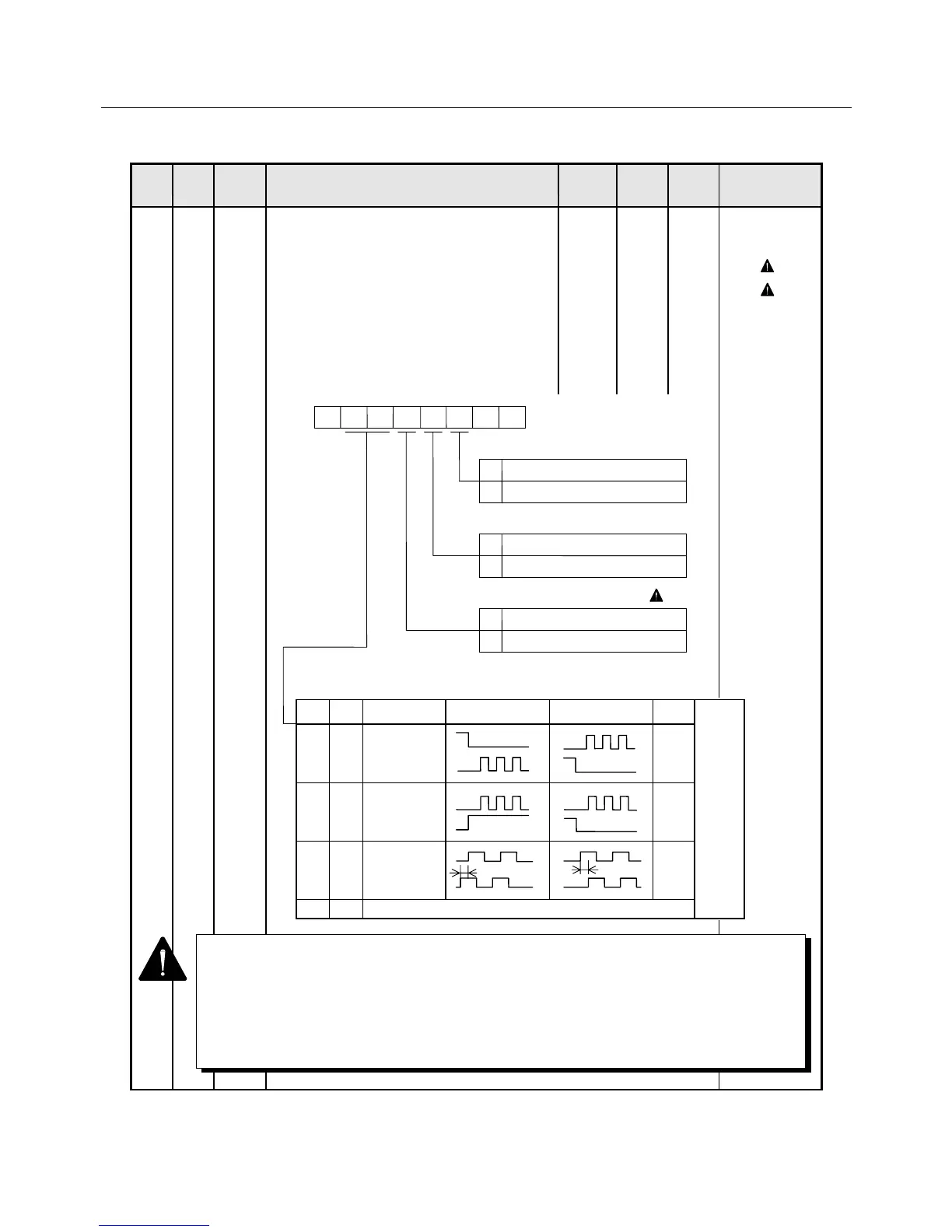
2 0 PMOD Position command pulse train form
• The position command pulse train can be
entered in 3 forms (forward revolution +
backward revolution pulse train, code + pulse
trains and 90° phase difference two-phase
pulse train).
Also, the rising/falling edge command, the
revolution direction and digital filter clock can
be specified.
0000-
0000
0, 1 Position control
( 1)
( 2)
1 For setting of bit7, bit1, and bit0, refer to the description provided on the following
and succeeding pages.
2 Only "0" and "0" are allowed to be set for bit3 and bit2 of the 90° phase difference
two-phase pulse train or the code + pulse train. (The rotating direction may vary.)
3 Bit4 of PMOD and bit2 of Func5 function the same.
When 1 is set to both bits, the system rotates forward (normal).
PMOD
012
345 6
7
1 1
Bit 6 Bit 5
Command
pulse form
Motor forward
revolution command
Motor backward
revolution command
CN1
0 0 Forward revolution
pulse train + back-
ward revolution
pulse train
28, 29
26, 27
1 0 Code + pulse train
28, 29
26, 27
0 1 90° phase
difference
two-phase pulse
train.
28, 29
26, 27
1 1 Prohibited
When the
revolution
direction
bit is set
at “0”.
“L”
“L”
“L”
90° 90°
0 Counts at the rising edge.
1 Counts at the falling edge.
CCWP input polarity switching
0 Counts at the rising edge.
1 Counts at the falling edge.
CWP input polarity switching
0 Standard.
1 Backward revolution.
Selection of revolution direction 3
“H”
 Loading...