7. EXPLANATION OF PARAMETERS
7-54
Mode Page
Abbre-
viation
Name and description
Standard
value
Unit
Setting
range
Remarks
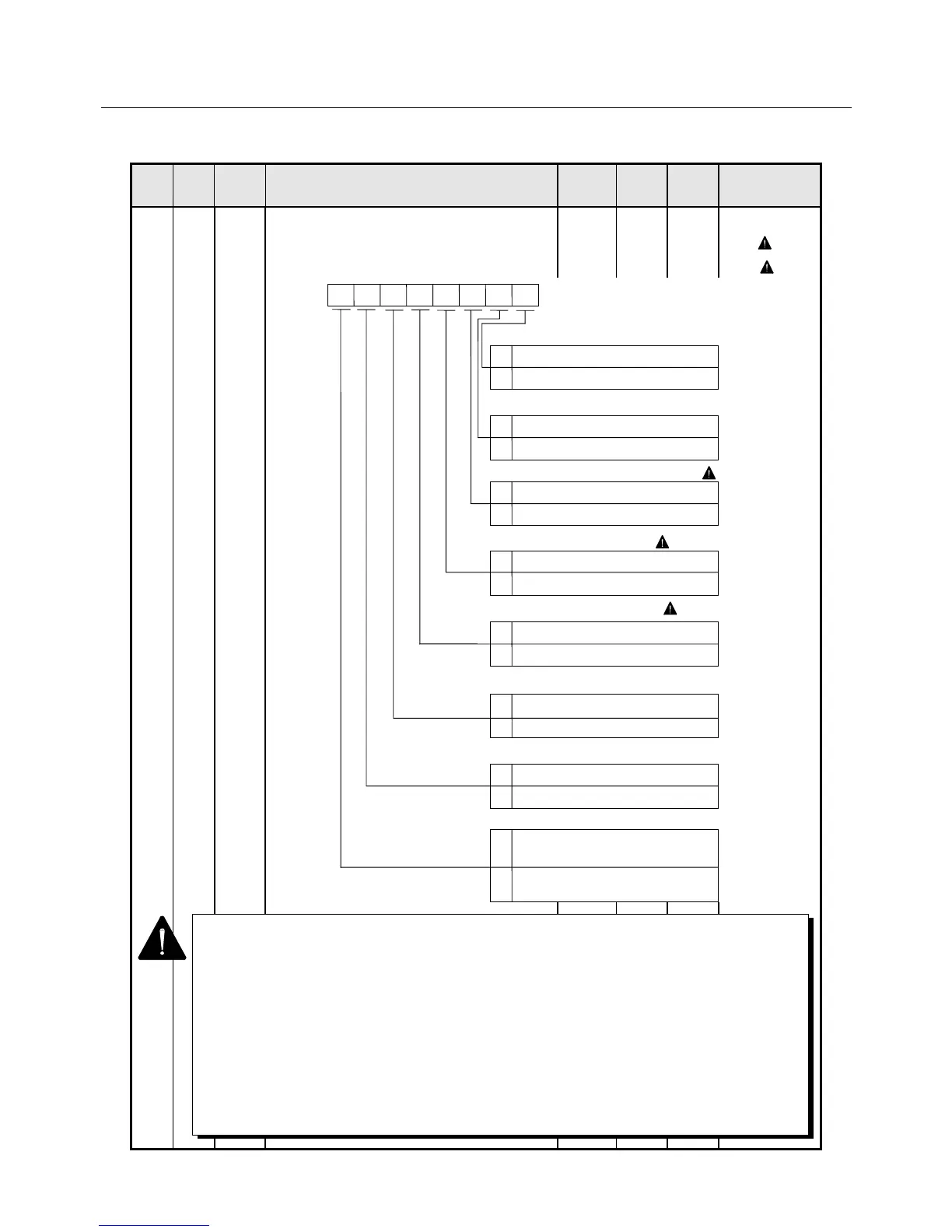
2 6 Func5 Amplifier function select 5
• Selects the encoder output format or the
command input polarity.
0000-
0000
0, 1
( 2)
( 3)
1 Even if you choose the fully closed encoder using the Func0 bit7 parameter, divided
output remains the same. Fully closed encoder can be used only on a servo system that
supports the fully closed design.
2 Before changing the setting of bits 7, 6, 5, 4 and 3, you must turn off the control power
once.
3 Forward revolution means counterclockwise revolution as viewed from the load (motor
shaft) side.
4 Bit3 is enabled when the ABS-RⅡ absolute sensor or Wiring-saved absolute sensor
ABS-E.S1 is used.
The number of incremental pulses to be output from CN1-3 to 8 pins can be selected.
5 Bit2 of Func5 and bit4 of PMOD function the same. When 1 is set to both bits, the
system is rotated forward at positive input.
Motor encoder A-/B-phase signal output phase switching
Position command polarity reversing bit ( 4)
Pulse generation output select ( 4)
Velocity command polarity reversing bit
Torque command polarity reversing bit
0 Forward revolution at positive input
1 Backward revolution at positive input
Func5
012
345 6
7
0 Forward revolution at positive input
1 Backward revolution at positive input
Divided output signal switching ( 1)
0 Forward revolution at positive input
1 Backward revolution at positive input
0 Motor encoder
1 Fully closed encoder
Encoder C-signal output logic select
0 A-phase signal not reversed
1 A-phase signal reversed
0 H active
1 L active
Serial signal output method select
0 Start-stop synchronization
(9600 bps)
1 Manchester coding synchronization
(1 Mbps or 2 Mbps)
0 2,048 P/R(8,192-division)
1 8,192P/R(32,768-division)
 Loading...