7. EXPLANATION OF PARAMETERS
7-55
Mode Page
Abbre-
viation
Name and description
Standard
value
Unit
Setting
range
Remarks
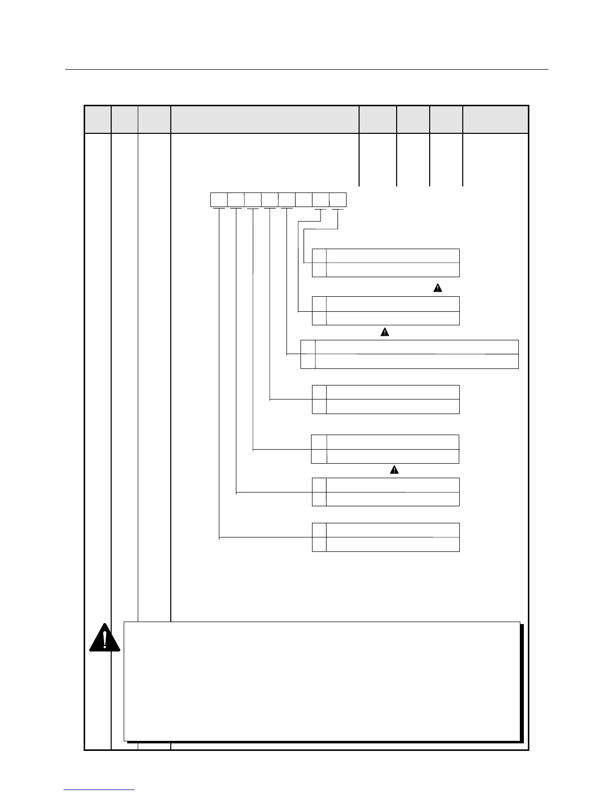
2 7 Func6 Amplifier function select 6
• This parameter is used for changing the
contents of parameters or permitting
execution of the test mode.
0000-
0000
0, 1
Note: Set bit2 to “0”.
* After operation, bits 7 and 6 must be set at "0" again. Turning off the control power also
returns bits 7, 6 and 4 to "0".
* If bit 0 is set at "1", alarm (memory error) will be indicated. After setting necessary
parameter, set bit 0 to "0", then turn power on.
1 Automatic switch function between proportional and proportional-plus-integral controls is
enabled by setting bit1 to “1”. When automatic switch function is enabled, control type is:
Proportional-plus-integral control when at or lower than set speed in LTG on page5 of
Mode1.
Proportional control when speed is higher than set speed in LTG on page5 of Mode1.
2 When using wiring-saved absolute sensor ABS-E.S1, multiple-rotational data will be
invalid by setting bit5 to “1” (1 rotational mode). When multiple-rotational data is not
required application, battery connection is not necessary. Set bit5 to “0” except for using
wiring-saved absolute sensor ABS-E.S1.
3 Cannot set bit5 and 3 without turning off the power once.
Parameter setup status
0 Set
1 Not set
Func6
012
345 6
7
P-PI automatic switching function ( 1)
0 Disabled
1 Enabled
Test mode alarm setting
0 Alarm enabled
1 Alarm disabled
Multiple-rotational processor select of
wiring-saved absolute sensor ABS-E.S1
0 Use multi-rotational part (normal)
1 Not using multi-rotational (1 rotation)
INP output setting ( 3)
0 Not permitted
1 Permitted
0 Disabled
1 Enabled
System parameter rewrite
Test mode execution ( 2)
0 Compare to command value after position command LPF
1 Compare to command value before position command LPF
 Loading...