84
Pin Assignment Chart
Female connectors COM1 and UniCOM:
25-pin D-Submini round female con-
nector (DB25S) with screw lock hard-
ware for:
Model SIWSDCS, stainless steel version
Front view
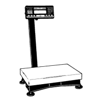
Pin Assignments in COM1
Round female connector with screw
lock hardware
Pin A: Control output: “lighter”
Pin B: Data output (TxD)
Pin C: Data input (RxD)
Pin D: Data terminal ready (DTR)
Pin E: Internal ground (GND)
Pin F: +5V
Pin G: Control output: “heavier”
Pin H: Clear to send (CTS)
Pin J: Control output: “equal”
Pin K: Universal remote switch
Pin L: Control output: “set”
Pin M: –12V
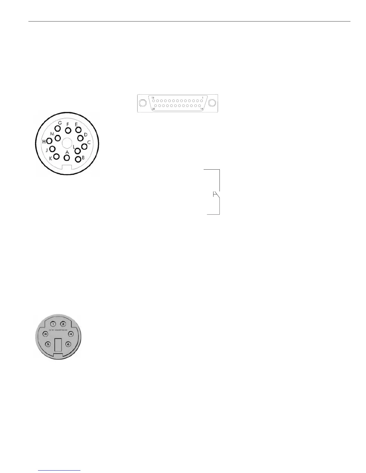
Pin Assignment for PS/2 Socket
for SIWDCS Standard Models
Round female connector
Pin 1: Keyboard clock
Pin 2: Keyboard data (data line)
Pin 3: Not connected
Pin 4: Internal ground (GND)
Pin 5: +5V
Pin 6: Not connected
* For SIWDCP models, application level 2
and higher.
Pin Assignment Chart
Female connectors COM1 and UniCOM:
25-pin RS-232 with screw lock hardware
Pin Assignments in COM1
Pin 1: Shield
Pin 2: Data output (TxD)
Pin 3: Data input (RxD )
Pin 4: Internal ground (GND)
Pin 5: Clear to send (CTS)
Pin 6: Internally connected
Pin 7: Internal ground (GND)
Pin 8: Internal ground (GND)
Pin 9: Not connected
Pin 10: Not connected
Pin 11: +12 V for printers
Pin 12: RES_OUT\
Pin 13: +5 V (on/off for bar code
scanner)
Pin 14: Internal ground (GND)
Pin 15: Universal remote switch
Pin 16: Control output: “lighter”
Pin 17: Control output: “equal”
Pin 18: Control output: “heavier”
Pin 19: Control output: “set”
Pin 20: Data terminal ready (DTR)
Pin 21: Power supply ground (GND)
Pin 22: Not connected
Pin 23: Not connected
Pin 24: Power supply +15 to 25 V
(peripherals)
Pin 25: +5 V
Required interface connector
(recommended):
25-pin D-Submini (DB25) with inte-
grated shielded cable clamp assembly
(Amp type 826 985-1C) and fastening
screws (Amp type 164868-1)
Connecting a Second Weighing
Platform
On Signum 2 and 3 models, you can
connect a second weighing platform to
either the COM1 or the UniCOM port.
COM1 operates in RS-232 mode.
A second weighing instrument on this
port can use the following operating
modes:
– SBI
– XBPI-232 (factory setting)
– ADC-232
UniCOM can operate in either the
RS-232 mode or in RS-485 mode.
A second weighing instrument on this
port can use the following operating
modes:
– SBI (RS-232 mode)
– XBPI-232 (RS-232 mode)
– ADC-232 (RS-232 mode)
– IS-485 (RS-485 mode, XBPI mode;
factory setting)
– ADC-485 (RS-485 mode)
– Second A/D converter using additional
interface (menu: comspec)
 Loading...