25
3.4 Device Setup Registers
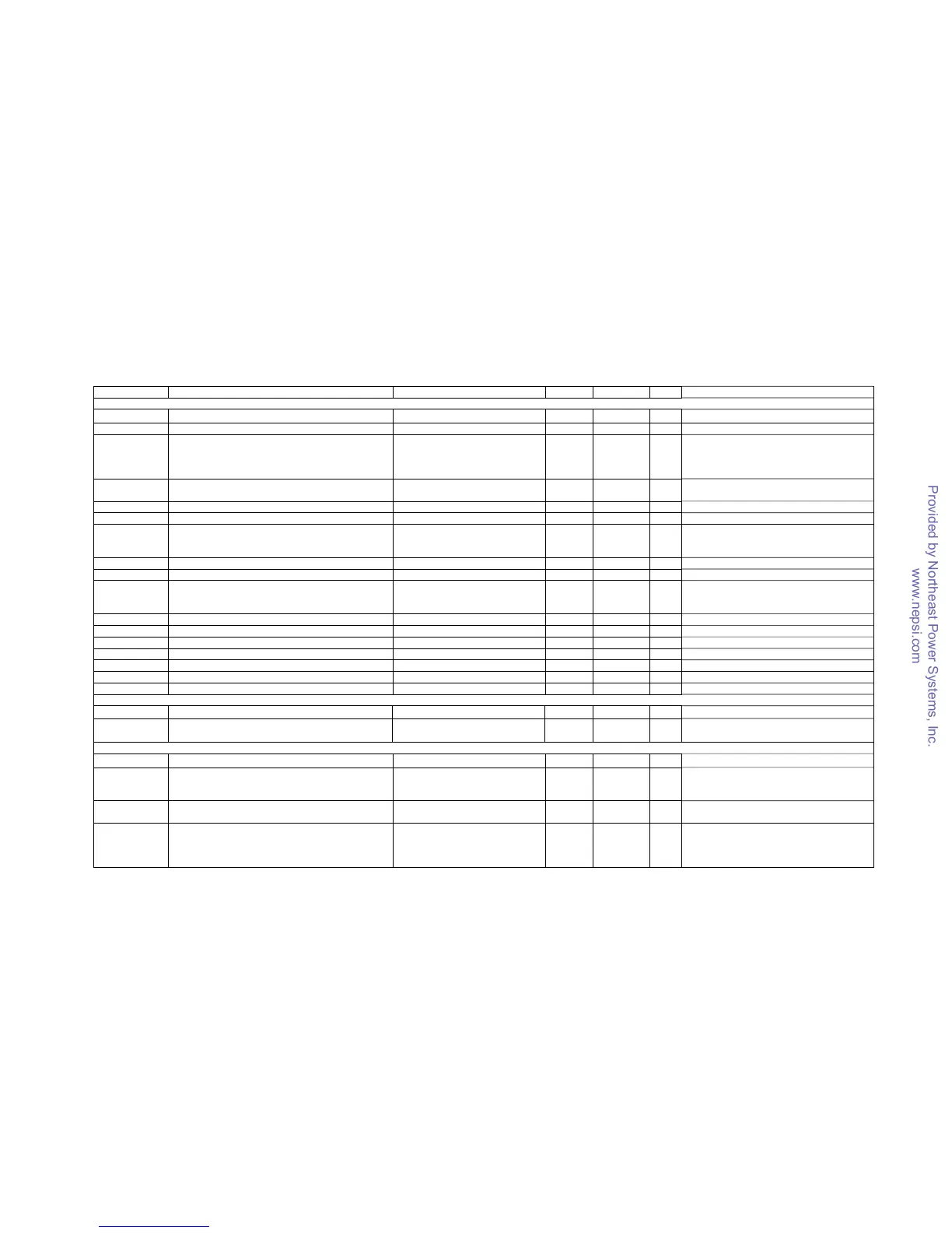
Address Description Options/Range Units Type R/W Notes
Factory Device Settings and Identification
0xFF40-0xFF5B
+0 Device serial number 0-999999 UINT32 R
+1 Device model ID 13010=PM130P, 13011=PM130A,
13020=PM130E,
13030-13032=PM130EH
13010=PM130P, 13030=PM130EH
UINT32 R
+2-5 Device model name “PM130P”, “PM130A”, “PM130E”,
“PM130EH”
UINT32 R Null-terminated string
+6 Device options (bitmap) 0 UINT32 R Not used
+7-9 Reserved 0 UINT32 R
+10 Device firmware version number 1101-1199 UINT16 R Two higher decimal digits = major version
number, two lower decimal digits = minor
version number
+11 Device firmware build number 1-99 UINT16 R
+12,13 Reserved UINT16 R
+14 Boot loader version number 101-999 UINT16 R Two higher decimal digits = major version
number, two lower decimal digits = minor
version number
+15 Boot loader build number 1-99 UINT16 R
+16-21 Reserved 0 UINT16 R
+22 V1-V3 inputs range 690 V UINT16 R
+23 V1-V3 inputs overload 120 % UINT16 R
+24,25 Reserved 0 UINT16 R
+26 I1-I3 inputs range 1, 5 A UINT16 R
+27 I1-I3 inputs overload 200 % UINT16 R
Device Data Scales
0x81F2
Voltage scale, in secondary volts
60-828 (default 144V) 1V UINT16 R/W
0x81F3
Current scale, in secondary amps = CT secondary
current (1A, 5A) × Current overload
20, 100 (2.0A, 10.0A)
×0.1A
UINT16 R
Communication Ports Setup
0x8500-0x851F
+0 Communication protocol COM1: 0=SATEC ASCII, 1=Modbus
RTU, 2=DNP3.0
COM2: 5=Profibus DP
UINT16 R
+1 Interface COM1: 1=RS-422, 2=RS-485
COM2: 7=Profibus
UINT16 R
+2 Device address SATEC ASCII: 0-99
Modbus RTU: 1-247
DNP3.0: 0-65532
Profibus: 0-126
UINT16 R

 Loading...


