Chapter 2 Installation Electrical Installation
PM135 Powermeter Series 23
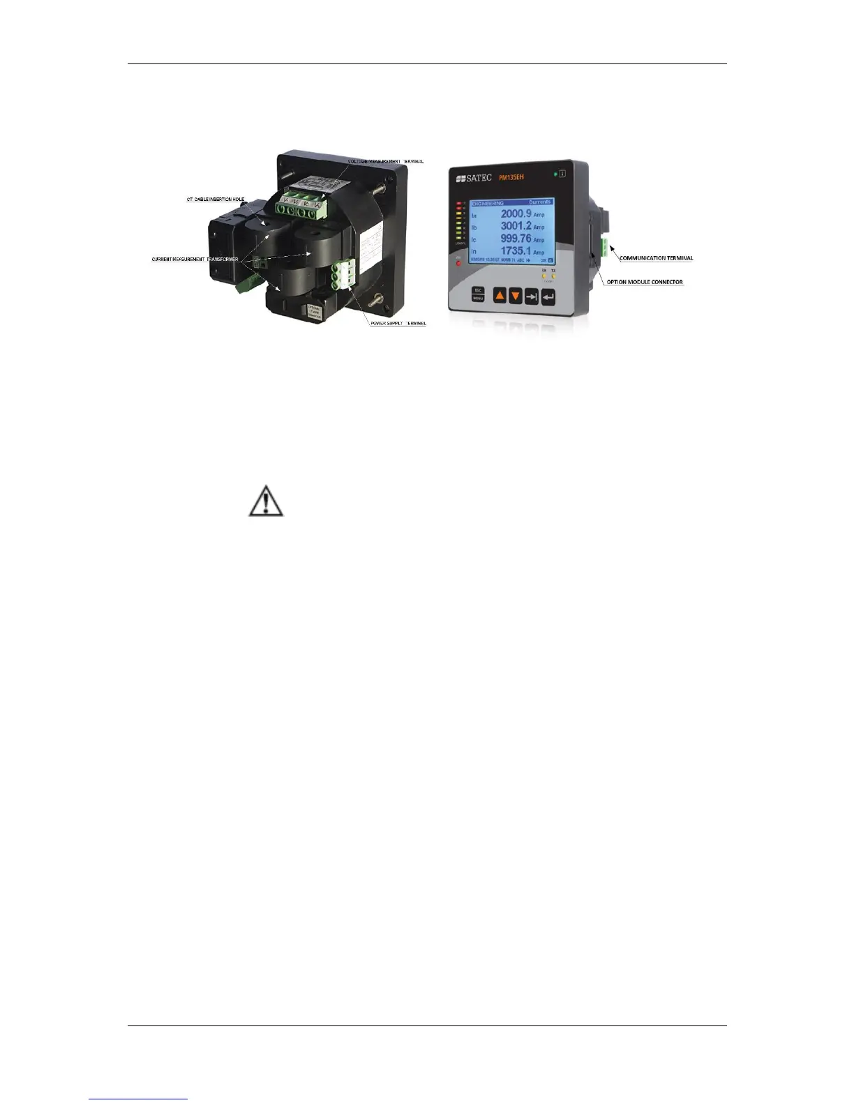
Terminals
Figure 2-7. Terminals -Rear View
Power Source Connection
The equipment installation shall conform to the following
instructions:
a) a switch or circuit-breaker shall be included in the building
installation;
b) It shall be in close proximity to the equipment and within
easy reach of the OPERATOR;
c) It shall be marked as the disconnecting device for the
equipment.
Before installing, ensure that all incoming power sources
are shut OFF. Failure to observe this practice can result in
serious or even fatal injury and damage to equipment.
The power source can be a dedicated fuse, or a monitored voltage if it is
within the instrument power supply range.
To connect an AC power supply:
1. Connect the Line wire to terminal
L/+.
2. Connect the Neutral wire to terminal
N/-.
To connect to a DC power supply:
1. Connect the positive wire to terminal
L/+
2. Connect the negative wire to
terminal N/-.