Chapter 5 Configuring the PM135 General Meter Setup
PM135 Powermeter Series 83
The maximum current scale
allowed, in secondary amps.
See Data Scales in Appendix F
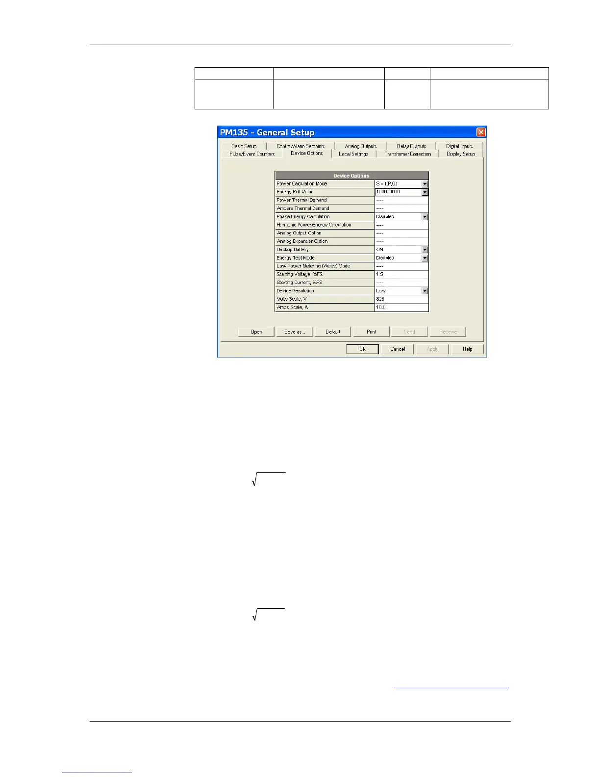
Figure 5-7: General Setup Dialog Box – Device Options Tab
Power Calculation Modes
The power calculation mode option allows you to change the method for
calculating reactive and apparent powers in presence of high harmonics.
The options work as follows:
When the reactive power calculation mode is selected, active and
reactive powers are measured directly and apparent power is
calculated as:
This mode is recommended for
electrical networks with low harmonic
distortion, commonly with THD < 5%
for volts, and THD < 10% for currents.
In networks with high harmonics, the
second method is preferable.
When the non-active power calculation mode is selected, active
power is measured directly, apparent power is taken as product S
= V x I, where V and I are the RMS volts and amps, and reactive
power (called non-active power) is calculated as:
Configuring Digital Inputs
The PM135 can be provided with four to twelve (depend on DI/O module
type) digital inputs that can be linked to control setpoints to give an
indication on input status change (see Configuring Alarm/Control