Chapter 2 Installation and Interfaces 7
If the instrument is installed in a harsh environment with potential for
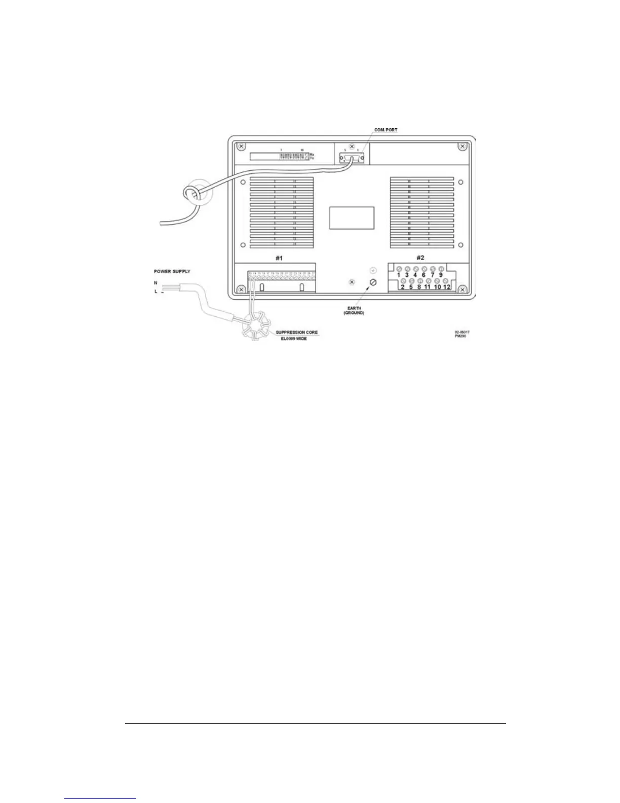
electromagnetic impulses from heavy switch gears, motors or lightning,
then it is mandatory to use the EMI/RFI suppression cores provided
with the instrument, connected to the power supply and communication
terminals, as shown in Figure 2-4.
Figure 2-4 Use of Suppression Cores
2.2.2 Power Source Connection
AC power supply: connect the live line of the power source to terminal
14 and the neutral to terminal 13.
DC power supply: connect the positive supply wire to terminal 14 and
the negative wire to terminal 13 (see Typical Installation on page iv).
2.2.3 Voltage Input Connections
660V Input: Direct Connection
Wiring diagrams for these are provided in Figures 2.5, 2.7, and 2.9.
660V Input: Using Potential Transformers
Wiring diagrams for applications where potential transformers (PT) are
used are provided in Figures 2-6 and 2-8.
120V Input
Instruments with 120V input (Option U) must be wired via potential
transformers. Wiring diagrams are provided in Figures 2-6 and 2-8.