Saia-Burgess Controls AG
Manual Manual PCD 1 / PCD 2 Series │ Document 26 / 737 EN22 │ 2013-11-26
CPUs and expansion housings
3-66
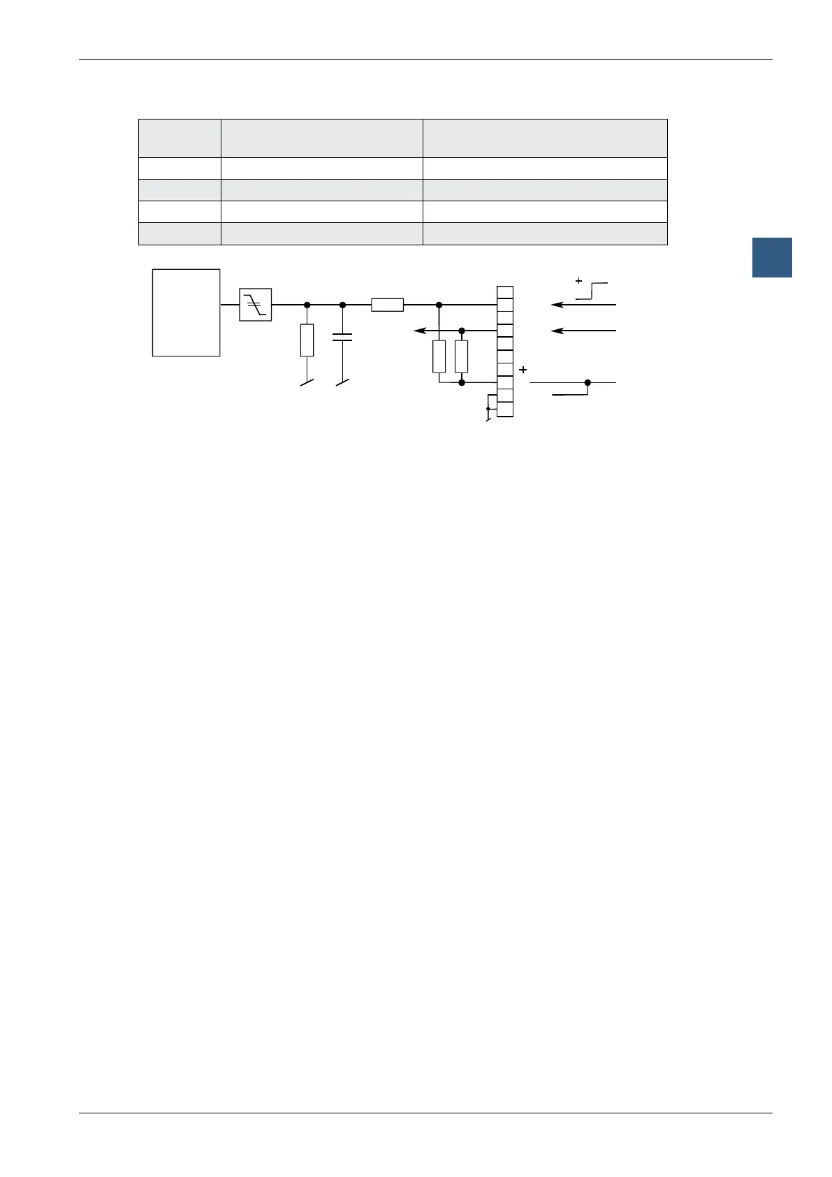
Interruptinputs
3
Interrupt
input
XOB called in case of a
positive edge
Input where the relevant XOB
is not programmed
IN0 XOB 20 I8100
IN1 XOB 21 I8101
IN2 XOB 22 I8102
IN3 XOB 23 I8103
Input signals (source operation):
H = 15.. 30 V
L = -30.. + 5 V or no connected
Input signals (sink operation):
H = 15 .. 30 V or no connected
L = -30.. + 5 V
source operation
(for sink operation
L at +24 V)
3.3 nF
µC
CF 5407
OutputsOUT4andOUT5canbeusedas“normal”,short-circuit-prooftransistor
outputs with addresses O 8104 and O 8105, and each loaded up to 0.5 A.
WheretheOUT4/OUT5outputsareused,the+connection(terminal6)musthavea
+24 V supply.