Mistral Operating Instructions
Part No. SCAZ037980 v6.0.2 10 E&OE
The CANbus system
The CANbus system comprises two control panels (main and auxiliary) an LCD monitor and a number of control nodes. The system controls and monitors all sweeper functions
and maintains a log of various operating parameters such as operating hours and any fault conditions that might occur.
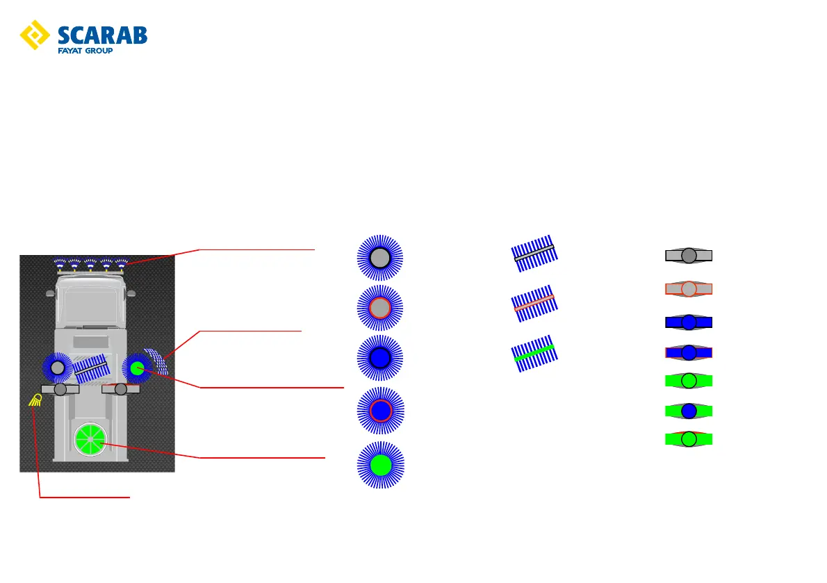
Switches: The various types of switch function are colour coded as follows:
RED = Critical functions, Sweep Mode ON/OFF.
AMBER = Electrical functions such as lighting.
GREEN = Sweeping functions.
BLUE = Water Spray functions.
Each switch illuminates a function-related symbol on the LCD monitor (only installed equipment will be displayed). Each symbol is greyed-out until its switch is activated. When
a switch is activated the appropriate symbol will illuminate according to system status as illustrated.
Brush not selected
Brush pre-selected
Water pre-selected
Brush and water
pre-selected
Operational
Brush not selected
Brush pre-selected
Operational
Nozzle not selected
Nozzle pre-selected
Water pre-selected
Nozzle and Water
pre-selected
Nozzle operational
Nozzle and water
operational
Nozzle tilt selected
Central brush water ON
Side brush water ON
Shown in the working position
Left work light ON
Suction fan ON (2000rpm)
 Loading...