Operating Manual Linear ACTUSAFE CMFS(L)
OM-ENGLISH-Failsafe-Linear-16xx-V2.00-2022.03.03 7 Parameter menu
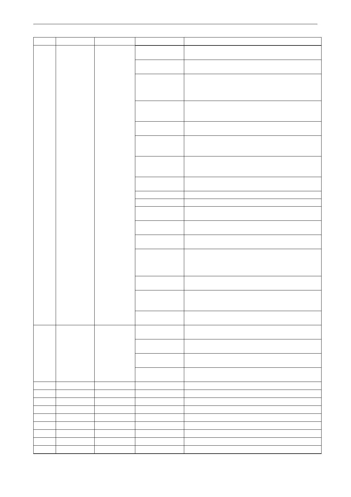
continued from previous page
Menu item Sub-menu item poss. setting Notes / comments
70: Analog In. 1
Fault
There is no or a faulty signal on the analog input 1.
71: Analog In. 2
Fault
There is no or a faulty signal on the analog input 2.
72: Phase
Sequence Fault
Cause on basis: Active phase sequence detection on
single phase actuators, loss of main power while
connected to external 24VDC auxiliary voltage, or loss of
phase 2.
73: Power Supply
Fault
No power supply to the power electronics (when the
controller is powered from the auxiliary power input).
Defect of power electronics.
74: Inverter Fault
The inverter is defective or the wiring is faulty (Only for
CM.V1.2 actuator series).
75: Manual
Override
Manual override is active (For FailSafe-Actuators); see
the FailSafe-section for more information about the
manual override.
76: Travel Sensor
Fault
The travel measurement is out of range or the wiring is
defective for AB CSC.V1.2 actuators. The travel sensor is
not calibrated for CM actuators.
77: Torque Sensor
Fault
Potentiometer fault on Basis, or cable is broken.
78: Bus Fault No communication with the optional bus.
79: Bus Watchdog Watchdog for bus communication has reacted.
80: Undervoltage
Warning
The input voltage is below the regular voltage range, but
motor operation is still possible.
81: Battery Low
Battery on display board is empty, loss of time/date or
counter values possible.
83: Undervoltage
Fault
The input voltage is too low, The motor is switched off,
until the input voltage is in the regular voltage range.
84: Undervoltage
Switchoff
The input voltage dropped below the lower threshold
multiple times. The motor is turned off for 5 minutes. This
error can be acknowledged by switching the selector
switch to OFF or by turning the actuator off and on.
85: Overvoltage
Warning
The input voltage is over the regular voltage range, but
motor operation is still possible.
86: Internal Fault
Internal communication error between electrical
components, i.e. Internal Comm.E error, or Internal
Comm.L error or Internal Comm.D error.
87: Torque Masked
Is set, if 33: Torque Open Mask or 34: Torque Close
Mask is set.
P10.2 Bin. Output Output conf. 1 0: normal
Output 1 is set to normal, i.e. if the condition in point
P10.1 is met, Output 1 is set to HIGH (active HIGH).
1: inverted
If the condition in point P10.1 is met, Output 1 is set to
LOW (active LOW).
2: norm. flashing
If the condition in point P10.1 is met, Output 1 starts
blinking (active HIGH).
3: inv. flashing
If the condition in point P10.1 is not met, Output 1 starts
blinking (otherwise it is set to HIGH).
P10.3 Bin. Output Output 2 see Output 1
P10.4 Bin. Output Output 2 Konf. see Output 1 conf.
P10.5 Bin. Output Output 3 see Output 1
P10.6 Bin. Output Output 3 Konf. see Output 1 conf.
P10.7 Bin. Output Output 4 see Output 1
P10.8 Bin. Output Output 4 Konf. see Output 1 conf.
P10.9 Bin. Output Output 5 see Output 1
P10.10 Bin. Output Output 5 Konf. see Output 1 conf.
P10.11 Bin. Output Output 6 see Output 1
continued on next page
55
 Loading...