OPERATION
XH1500/XH1000 06-24 Operation Section 4-14
OPERATION
© 2024 Alamo Group Inc.
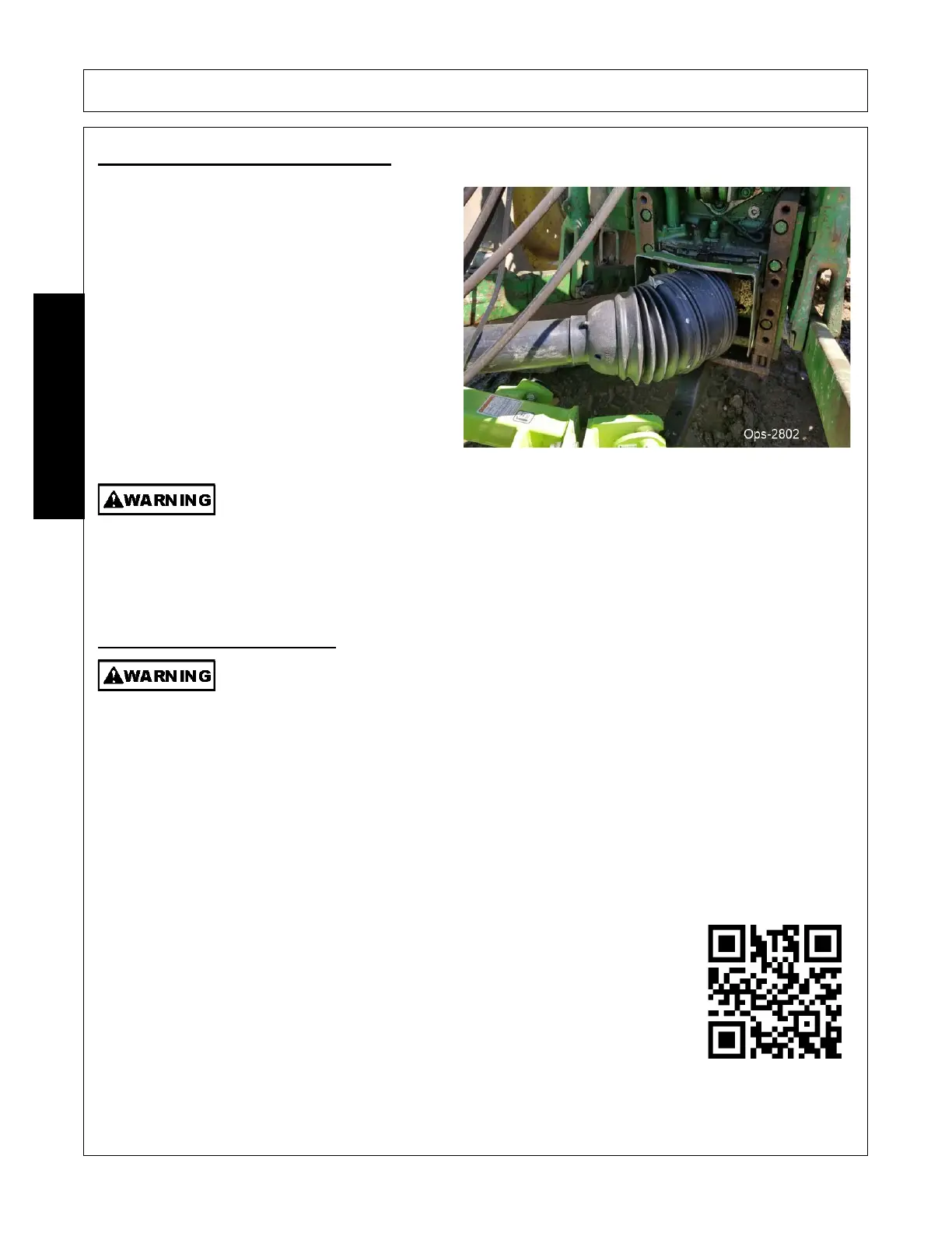
7. DRIVELINE ATTACHMENT
Connect the universal joint assembly to the tractor
PTO. Align the quick disconnect yoke splines with
the tractor PTO splines. Twist the lock collar and
slide the yoke into place. Twist the collar back to
lock on the PTO shaft.
IMPORTANT: Pull and push on the quick
disconnect yoke several times to ensure that the
yoke is connected to the PTO shaft.
When attaching the Implement input driveline to the Tractor PTO, it is important that the
connecting yoke spring activated locking collar slides freely and the locking balls are seated
securely in the groove on the Tractor PTO shaft. Push and pull the driveline back and forth
several times to ensure it is securely attached. A driveline not attached correctly to the Tractor
PTO shaft could come loose and result in personal injury and damage to the Implement.
(S3PT-
17 str)
7.1 Driveline Length Check
Before operating the Implement, check to make sure the Implement input driveline will not
bottom out or become disengaged. Bottoming out occurs when the inner shaft penetrates the
outer housing until the assembly becomes solid-it can shorten no more. Bottoming out can
cause serious damage to the Tractor PTO by pushing the PTO into the Tractor and through
the support bearings or downward onto the PTO shaft, breaking it off. A broken driveline can
cause personal injury.
(S3PT-18 str)
When fitting the mower to the tractor, the telescoping driveline must be inspected to ensure that at its most
compressed position, the profiles do not “bottom out”, and when at its farthest extended position, there is
sufficient engagement between the profiles to operate safely. At its shortest length, there must be at least a 1”
clearance between each profile end and opposite profile universal joint. At its farthest extension, a minimum
profile engagement of 6” must be maintained for a Constant Velocity (CV) tube type driveline and a minimum
engagement of 6” for non-CV solid shaft drivelines.
IMPORTANT: Scan this QR Code with your smart phone to link to the ADMA Driveline
Safety Manual for more information on the safe use of a driveline during normal
operation and maintenance. Or type in your internet browser the following web
address: www.algqr.com/dme
Ops-0009-MISC str
 Loading...