Assembly
06.00 | DRG | Assembly and operation manual | en | 389041 19
5.2 Connections
5.2.1 Mechanical connection
Evenness of the
mounting surface
The values apply to the whole mounting surface to which the
product is mounted.
Edge length Permissible unevenness
< 100 < 0.02
> 100 < 0.05
Tab.: Requirements for evenness of the mounting surface (Dimensions in mm)
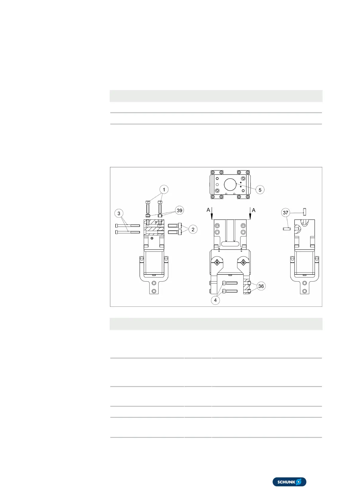
Mounting
The module can be mounted from the front, from the rear, and
from below:
Assembly options
Item
Mounting 44 54 64 80 100
1 Module from
below
M4 x
max. 9
M5 x
max. 12
M6 x
max. 14
M6 x
max. 14
M10 x
max.
20
2 Module from the
rear
M4 x
max. 7
M5 x
max. 10
M6 x
max. 12
M8 x
max. 16
M10 x
max.
20
3 Module from the
front
- M4 x 40 M5 x 45 M5 x 55 M8 x
65
4 Top jaws M3 M4 M5 M6 M8
5 Centering
diameter
20
H7
20
H7
25
H7
30
H7
-
Tab.: Mounting material