Assembly
28 14.00 | GSM-P | Assembly and Operating Manual | en | 389104
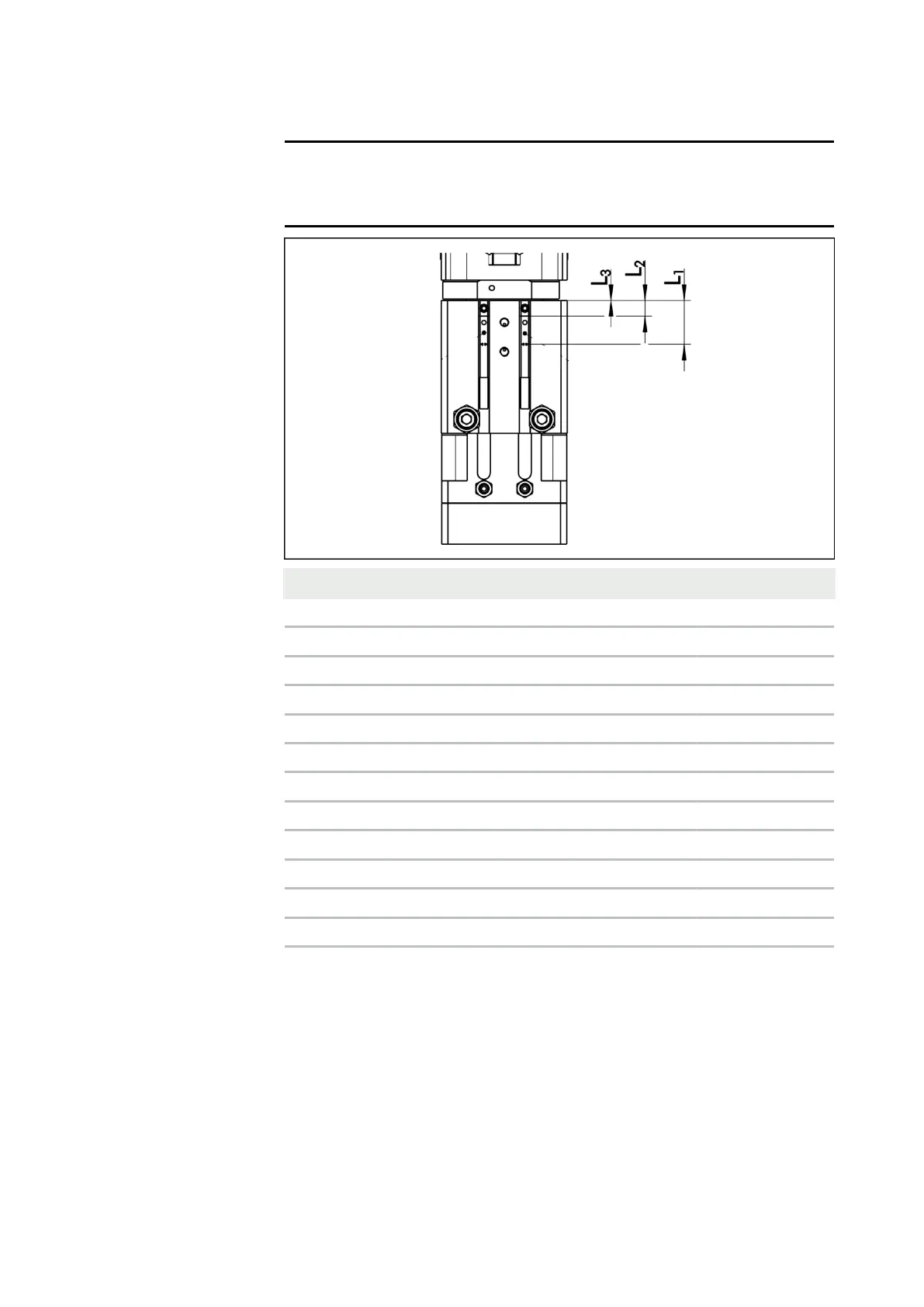
5.3.3 Settings for magnetic switch
NOTE
The installation dimensions shown only apply if the clamping
position of the sensor is not specified by a T-nut.
GSM Type Dimension L1 Dimension L2 Dimension L3
GSM-P-32 8.9 0 -
GSM-P-32-AS 8.9 0 -
GSM-P-32-IS 20.05 11.15 6.15
GSM-P-40 13.9 5 0
GSM-P-40-AS 13.9 5 0
GSM-P-40-IS 31.5 22.6 17.6
GSM-P-50 16.9 8 3
GSM-P-50-AS 16.9 8 3
GSM-P-50-IS 36.7 27.8 23
GSM-P-64 13.9 5 0
GSM-P-64-AS 13.9 5 0
GSM-P-64-IS 26.25 16.35 11.35
Tab.: Installation dimensions for MMS-P