Maintenance
14.00 | GSM-P | Assembly and Operating Manual | en | 389104 57
8.12 Drawings
The following figures are example images.
They serve for illustration and assignment of the spare parts.
Variations are possible depending on size and variant.
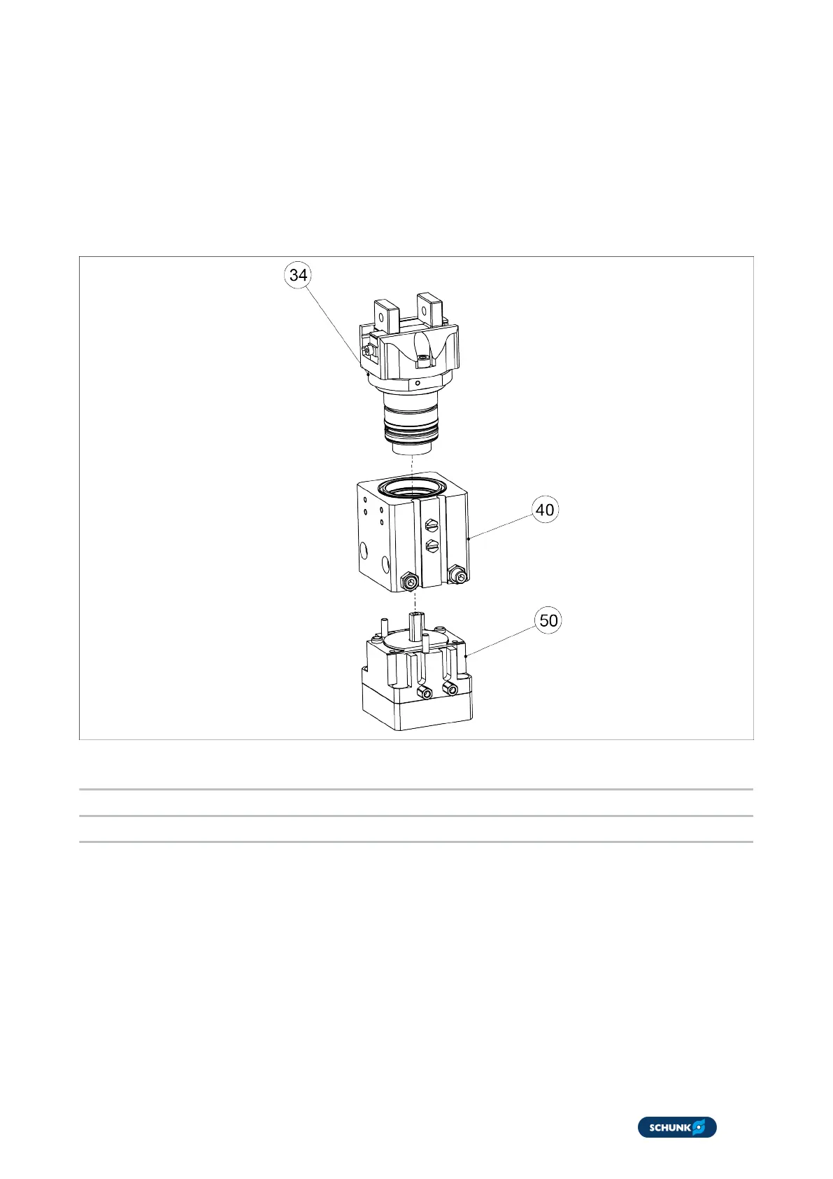
8.12.1 Assembly drawing of the basic module
Basic module overview
34 PGM gripping module
40 DKM feed-through compact module
50 FAN rotor drive