Assembly
32 14.00 | GSM-P | Assembly and Operating Manual | en | 389104
5.3.6 Inductive monitoring via IN 40
GSM-P Attachment kit for INW 40 ID
number
AS-GSM-P-32, attachment kit for IN 40 0304934
AS-GSM-P-40, attachment kit for IN 40 0304935
AS-GSM-P-50, attachment kit for IN 40 0304936
AS-GSM-P-64, attachment kit for IN 40 0304937
Tab.: Attachment kits for IN 40
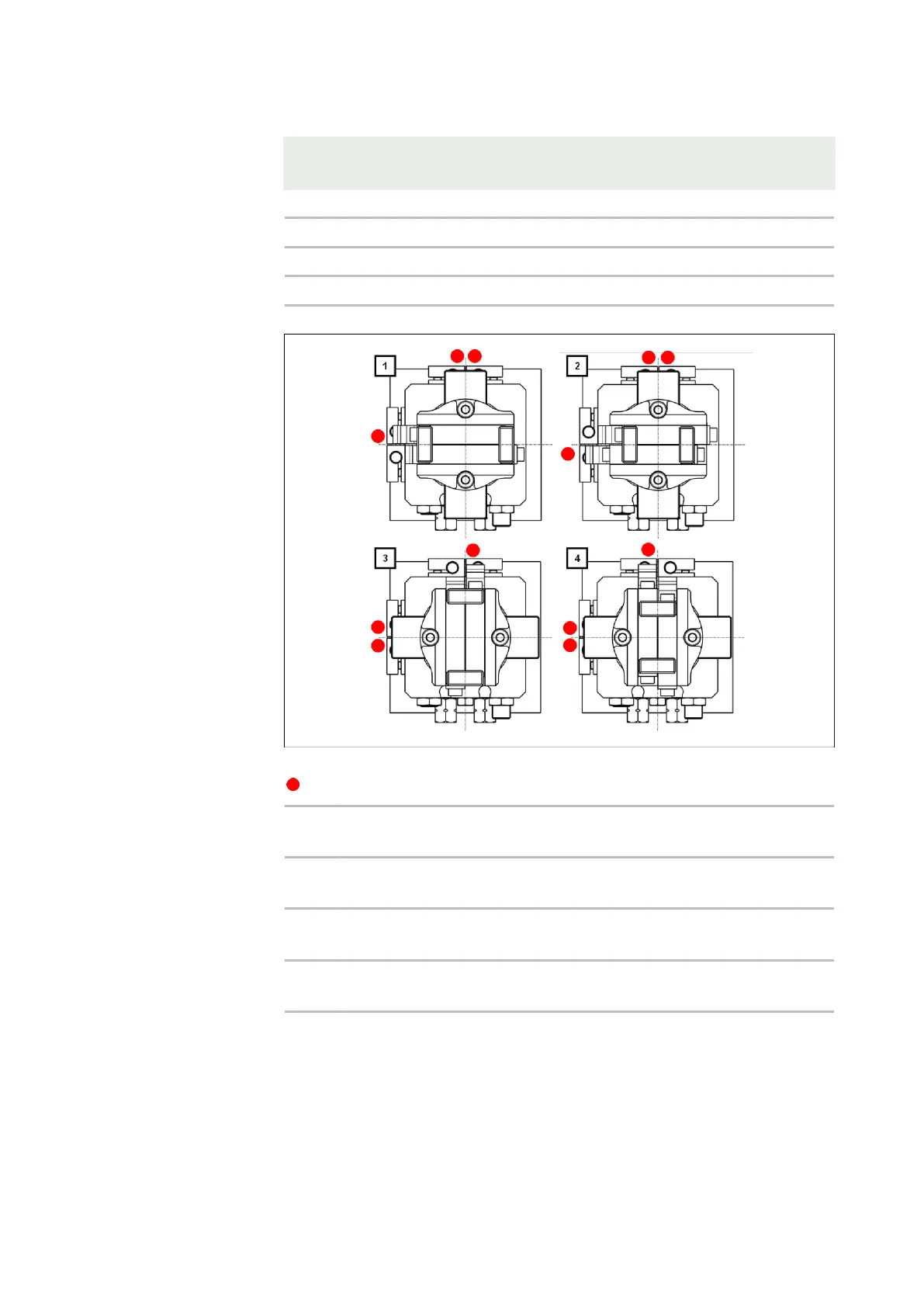
Schematic diagram of
inductive monitoring
with IN 40 for GSM for
090 variants
Schematic diagram of inductive monitoring with IN 40 of GSM
Dampened sensor
[1] Rotating angle end position in counterclockwise direction
with opened gripper
[2] Rotating angle end position in counterclockwise direction
with closed gripper
[3] Rotating angle end position in clockwise direction with
opened gripper
[4] Rotating angle end position in clockwise direction with closed
gripper