Assembly
14.00 | GSM-P | Assembly and Operating Manual | en | 389104 33
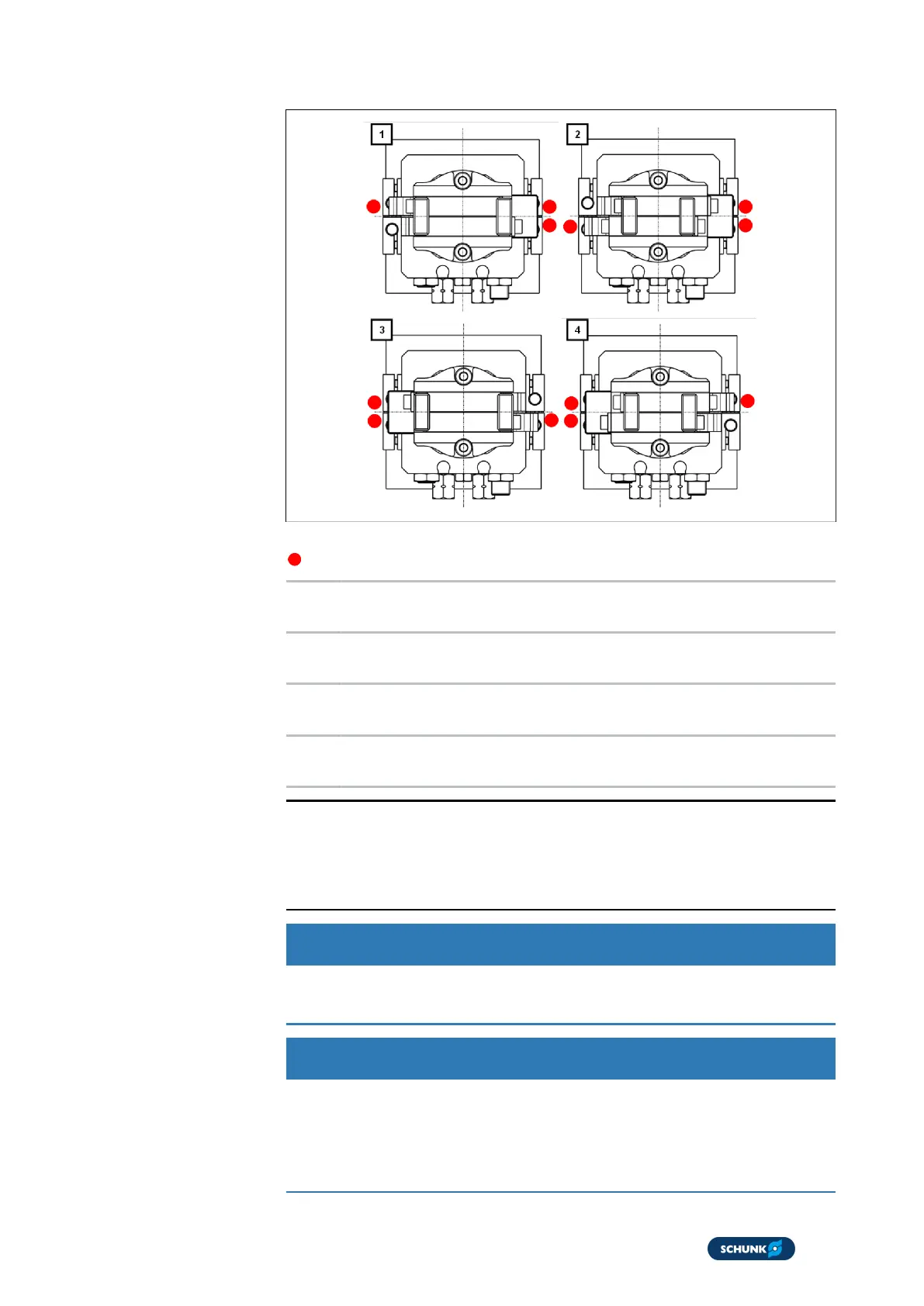
Schematic diagram of
inductive monitoring
with INW 40 for GSM
for 180 variants
Schematic diagram of inductive monitoring with IN 40 of GSM
Dampened sensor
[1] Rotating angle end position in counterclockwise direction
with opened gripper
[2] Rotating angle end position in counterclockwise direction
with closed gripper
[3] Rotating angle end position in clockwise direction with
opened gripper
[4] Rotating angle end position in clockwise direction with closed
gripper
NOTE
One of the two inductive proximity switches for the "gripping"
monitoring is briefly crossed over during swiveling action by
"second switching lug gripping".
CAUTION
The maximum tightening torque for the clamping screws (301
and/or 303) at the holder (300) is 125 Ncm. Remove bracket (8).
CAUTION
Risk of damage due to incorrect adjustment of the proximity
switches!
Disconnect the energy supply before installing or adjusting the
inductive proximity switches.