Assembly
30 14.00 | GSM-P | Assembly and Operating Manual | en | 389104
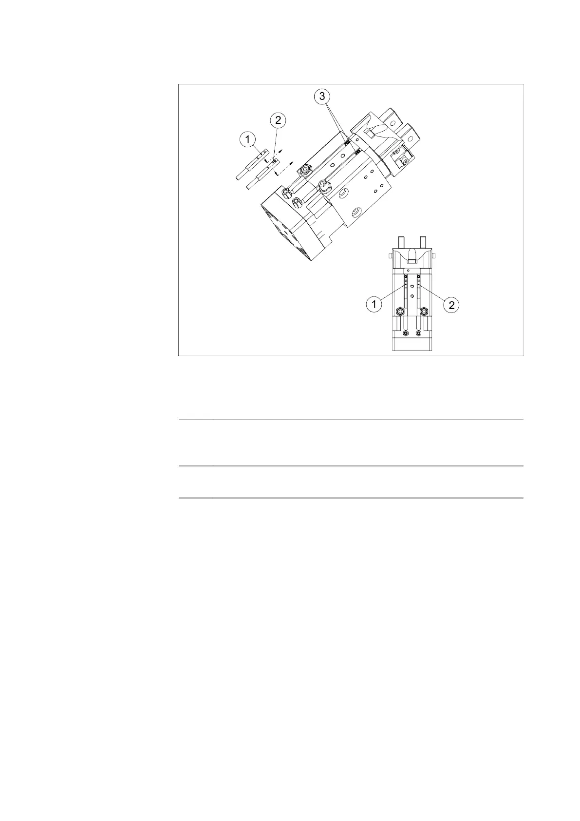
5.3.5 Assembly and setup of the MMS-P 22
Position and installation of the MMS-P magnetic switches
1 Sensor MMS-P
(groove 1)
Monitoring gripper position 1 and gripper
position 2 in the left rotating angle end
position (signals SGL1 and SGL2)
2 Sensor MMS-P
(groove 2)
Monitoring gripper position 1 and gripper
position 2 in the right rotating angle end
position (signals SGR1 and SGR2)
3 Stop for MMS-P Determining the clamping position of the
MMS-P sensor
Monitoring GSM locations/positions/end positions:
SGL1: left rotating angle end position, gripper position 1
SGL2: left rotating angle end position, gripper position 2
SGR1: right rotating angle end position, gripper position 1
SGR2: right rotating angle end position, gripper position 2
2 gripper positions can be monitored by each of the two MMS-P
sensors. If the gripper is in a third gripper position, the rotating
angle end position can only be monitored via additional sensors.
 Loading...