Assembly
14.00 | GSM-P | Assembly and Operating Manual | en | 389104 23
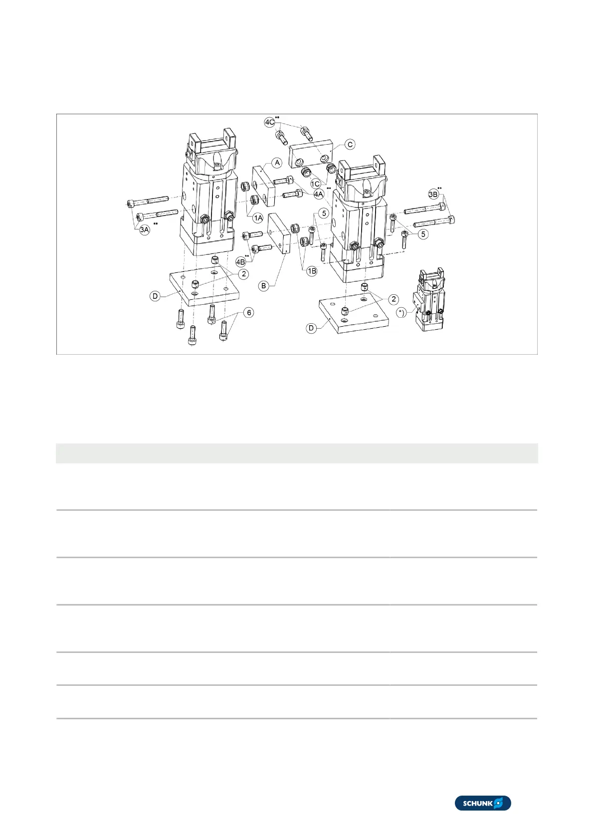
5.2 Connections
5.2.1 Mechanical connection
Mounting the GSM on the side and base side
*
*
To ensure the function of the sensors, the A2 screws from the
accessory pack are to be used.
For process-reliable monitoring, adapter plates should be made
of non-ferromagnetic material.
Item GSM - SFL basic size 40 64
1A
1B
1C
Centering sleeve for lateral mounting of the unit and
fitting depth in the mounting plate
Ø8
2.5 deep
Item 206
Ø10
3 deep
Item 205
2 Centering sleeve for mounting the unit on the base side
and fitting depth in the mounting plate
Ø6
2.5 deep
Item 205
Ø10
3 deep
Item 205
3A
3B
3C
Thread diameter for screwing through for mounting the
unit at the side
M4
Item 232
M5
Item 232
4A
4B
4C
Thread diameter and max. depth of engagement for
screw connection for lateral mounting
M5
19 deep
Item 231
M6
25 deep
Item 231
5 Thread diameter for screwing through for mounting the
unit on the base side
M3 M5
6 Thread diameter and maximum depth of engagement for
screw connection for mounting on the base side
M4
8 deep
M6
11 deep
 Loading...