Maintenance
40
11.00 | PGN | Assembly and Operating Manual | en | 389286
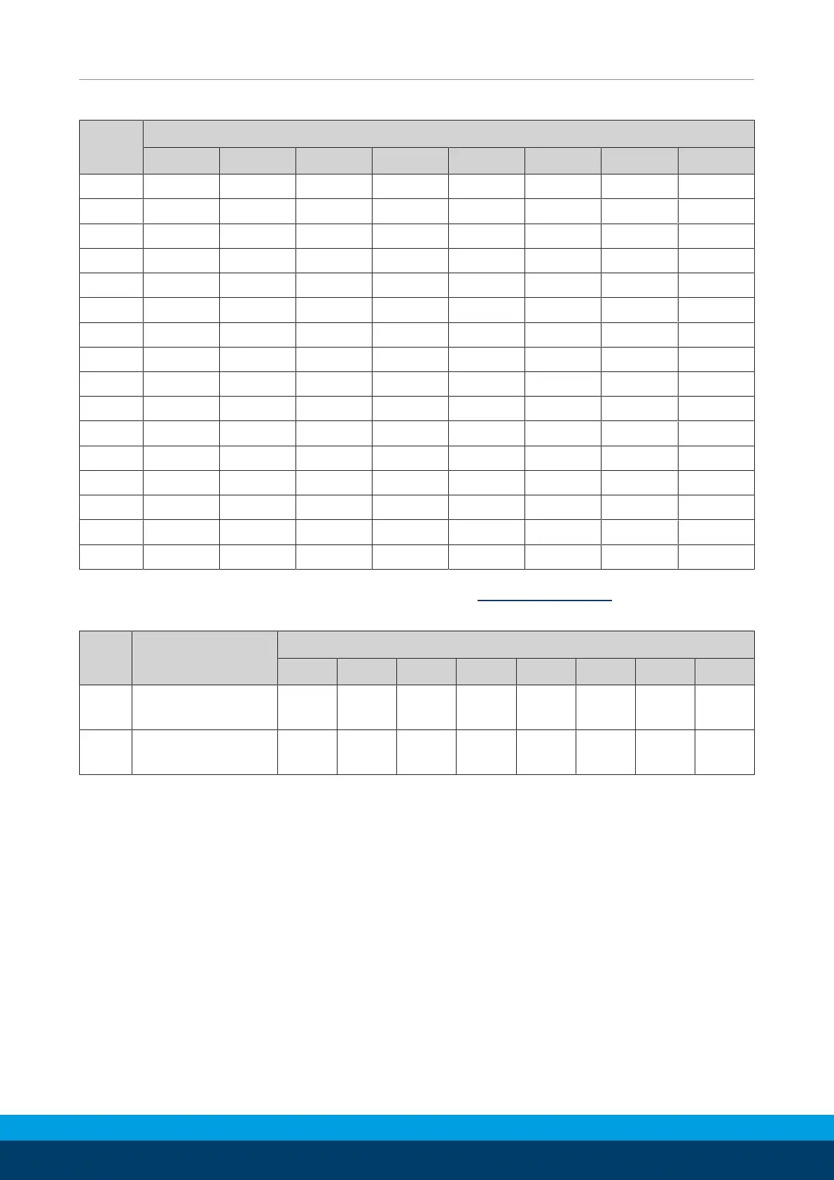
Mounting device cylinder piston - dimensions in mm
PGN
50 64 80 100 125 160 200 300
A 45 56 66 80 104 125 150 210
B 32 40 46 53 64 78 100 140
C 27 30 60 60 60 70 70 68
d
1
- - 66 80 - - 150 200
d
3
- - 6.6 9 - - 11 11
d
4
H7 21 26 34 42 52 64 90 127.5
d
5
8 10 10 11 15 15 18 26
d
6
- - M6 M8 - - M10 M10
d
7
4.5 5.5 5.5 6.6 9 9 11 17.5
d
8
H7 3 4 4 5 6 6 8 10
d
9
- - 33 41 - - 89 126
l
1
- - 52 66 - - 130 180
l
2
35 42 52 66 82 100 130 180
l
4
22 27 32 38 45 56 70 95
l
5
5 6 8 10 10 12 16 16
l
6
4.5 6 6 7 9 9 11 17.5
Position of the item numbers Assembly drawing [
}
44]
Screws for assembly device
Item Designation PGN
50 64 80 100 125 160 200 300
102 Screw
(DIN EN ISO 4762)
M4 x
25
M5 x
30
M5 x
60
M6 x
60
M8 x
60
M8 x
70
M10 x
80
M16 x
70
103 Screw
(DIN EN ISO 4762)
- - M6 x
40
M8 x
40
- - M10 x
55
M10 x
40
 Loading...


