04.00|0889071 ROTA TP / ROTA TP-LH |en
Mounting
Installing and connecting
Risk of injury due to unexpected movements!
If the power supply is switched on or residual energy remains in
the system, components can move unexpectedly and cause
serious injuries.
• Before starting any work on the product: Switch off the power
supply and secure against restarting.
• Make sure, that no residual energy remains in the system.
Danger of injury due to sharp edges and rough or slippery
surfaces
• Wear personal protective equipment, particularly protective
gloves.
Always use the correct length of mounting screws when
mounting the chuck and flange. Screws that are too long may
protrude from the tapping drill hole or damage the machine
spindle.
1 Preparing the mount ( 6.2, Page 35)
2 Chuck assembly ( 6, Page 35)
3 Performing a functional check ( 4.2, Page 29)
Inclusion
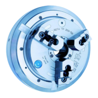
For ROTA TP 125 / Z up to 350 / Z lathe chuck types, a normal
intermediate flange must be placed on the spindle head. Using 6
pin screws M12 x 40 (sizes 160 - 350), the rear flange side of the
front of the power chuck which has been turned free is screwed
»across corners« into the intermediate flange which has been
screwed into the spindle head. The cylindrical precisely turned
centering shoulder on the flange must be screwed on 6
−2
mm
deep so as to ensure contact with the outer chuck edge. In order