12
S100-F / ITB-F I&O Manual
IM101230
RD: JAN 2014
RL: 9A
* RECOMMENDED MOUNTING HEIGHTS are typical to provide optimum comfort in general
space heating applications. Variance to these typical heights can occur in some applications:
Higher mounting heights due to structure or application requirements
Lower mounting heights for area or ‘spot’ heat, or in areas with greater infiltration losses
(near overhead doors, etc)
IMPORTANT: Single or multiple heater placement must be such that continu-
ous operation of heater(s) will not cause combustible material or materials in
storage to reach a temperature in excess of ambient temperature plus 90F°
(50C°).
It is the installer’s responsibility to ensure that building materials with a
low heat tolerance which may degrade at lower temperatures are pro-
tected to prevent degradation. Examples of low heat tolerance materials
include vinyl siding, fabrics, some plastics, filmy materials, etc.
Refer to “Clearance to Combustibles” information on pages 6 to 8, and
Figure 1 and Table 1.
MOUNTING
HEIGHT
ft (m)
MAXIMUM
DISTANCE
BETWEEN
HEATERS
ft (m)
DISTANCE – OUTSIDE WALL
TO HEATER LONG AXIS
(PARALLEL TO WALL) IN “FEET”
HORIZONTAL
ft (m)
ANGLE
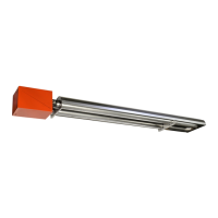
S100 / ITB 200
18 – 25 (6 - 8) 50 (15) 17 – 25 (5 - 8)
COMBUSTIBLE
CLEARANCE
BEHIND
(refer to Table 1)
S100 / ITB 175
18 – 25 (6 - 8) 50 (15) 17 – 25 (5 - 8)
S100 / ITB 155
16 – 21 (5 - 7) 45 (14) 15 – 20 (5 - 7)
S100 / ITB 130
15 – 21 (5 - 7) 40 (12) 15 – 20 (5 - 7)
S100 / ITB 110
13 – 19 (4 - 6) 35 (11) 13 – 18 (4 - 6)
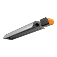
MODEL
“Straight” or
“U-Tube”
S100 / ITB 80
10 – 16 (3 - 5) 30 (9) 12 – 16 (4 - 5)
S100 / ITB 60
8 – 14 (2.5 - 5) 25 (8) 11 – 15 (3.4 - 5)
S100 / ITB 45
8 – 12 (2.5 - 4) 20 (6) 8 – 12 (2.5 - 4)
S100 / ITB 100
13 – 19 (4 - 6) 35 (11) 13 – 18 (4 - 6)
TABLE 2: GUIDELINES FOR HEATER PLACEMENT
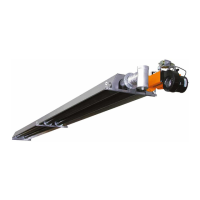
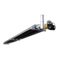
7. SYSTEMS INCORPORATING 90° ELBOWS AND 180° ELBOWS
The radiant tube heater can be installed in configurations as illustrated in FIGURE 4. (below)
with a maximum of two 90° elbows per heater. The use of elbows reduces the total maximum
vent allowable. (See Section 11 : Flue venting)
 Loading...