7
S100-F / ITB-F I&O Manual
IM101230
RD: JAN 2014
RL: 9A
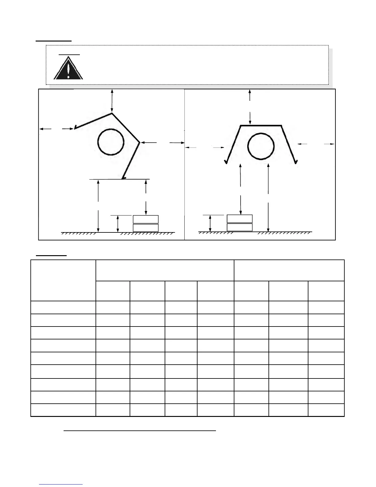
TABLE 1 MINIMUM CLEARANCES TO COMBUSTIBLES*
FIGURE 1 MINIMUM CLEARANCES TO COMBUSTIBLES* - refer to Table 1 for values
*NOTE: Clearances are measured from the reflector.
The clearance to combustible materials represents the minimum distance that must be main-
tained between the heater and a nearby surface. The stated clearance to combustibles
NOTE: A ‘PEEL & STICK’ SIGN IS SUPPLIED: USE AN INDELIBLE MARKER TO
ENTER VALUES ‘H’, ‘S’, ‘F’, & ‘B’ ON .
POST THE SIGN ADJACENT TO THE HEATER THERMOSTAT OR IN A
PROMINENT LOCATION.
See next page for details.
S
S
FLOOR
H
T
H
Maximum
Stack Height
H = T- C
‘T’ is meas-
ured on site,
‘C’ is in Table
FLOOR
MODEL
BOTH “STRAIGHT”
& “U-TUBE
SUSPENDED AT AN ANGLE
UP TO 45 DEGREES
SUSPENDED
HORIZONTALLY
D
inches (cm)
B
inches (cm)
F
inches (cm)
C
inches (cm)
A
inches (cm)
S
inches (cm)
C
inches (cm)
S100(U)/ITB(U) 200 13 (33)
6 (15.2)
74 (188) 70 (178) 14 (36) 44 (112) 76 (193)
S100(U)/ITB(U) 175 12 (31)
6 (15.2)
72 (183) 68 (172) 13 (33) 42 (107) 74 (188)
S100(U)/ITB(U) 155 10 (26) 4 (10) 50 (112) 64 (163) 11 (28) 34 (87) 64 (163)
S100(U)/ITB(U) 130 9 (23) 3 (8) 40 (102) 56 (142) 10 (26) 32 (81) 60 (152)
S100(U)/ITB(U) 110 9 (23) 3 (8) 36 (92) 54 (137) 9 (23) 30 (76) 60 (152)
S100(U)/ITB(U) 80 7 (18) 2 (5) 31 (79) 38 (97) 7 (18) 24 (61) 42 (107)
S100(U)/ITB(U) 60 7 (18) 2 (5) 25 (64) 34 (86) 7 (18) 20 (51) 34 (86)
S100(U)/ITB(U) 45 7 (18) 2 (5) 29 (74) 32 (81) 7 (18) 16 (41) 32 (81)
S100 /ITB 100 10 (26) 4 (10) 57 (145) 68 (172) 11 (28) 32 (81) 68 (172)
T
C
Maximum
Stack Height
H = T- C
‘T’ is meas-
ured on site,
‘C’ is in Table
B
F
D
Suspended at an
angle up to 45°
C
Suspended
horizontally
A