17
S100-F / ITB-F I&O Manual
IM101230
RD: JAN 2014
RL: 9A
9.2 S100U / ITBU ‘U’-TUBE SYSTEM ~ BURNER AND TUBE INSTALLATION
For “Straight-Tube” Systems S100 / ITB refer to section 9.1 page 15
IMPORTANT SPECIAL NOTES: READ FIRST
1. S100U/ITBU 175 & 200: Special Tube Coupling - Refer to Section 9.4, Fig 16
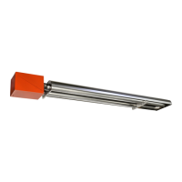
These input rates have an unpainted titanium alloy stainless steel first tube with a
flange (painted “white”), and an unpainted aluminized steel tube as the second tube; all
subsequent tubes are hot rolled steel. The first tube (titanium alloy stainless steel ) will
“glow red” while heater is in operation - THIS IS A NORMAL CONDITION
2. TURBULATORS: Also refer to Table page 47
155 Models (150,000 Btuh): 2 ft turbulator is supplied in the Burner Kit and field installed:
155 x 20 ft U heater: Insert 2 ft turbulator in end of third tube in the system (1st
tube after turn box), prior to the 10 ft turbulator that is factory installed in the last
tube (total 12 ft turbulator)
155 x 30 ft U heater: Discard 2 ft turbulator - not required.
All other turbulators are factory installed inside tube(s) that are clearly labeled with
instruction as to where the tube(s) must be installed - Also see page 47
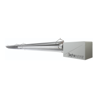
FIGURE 9 COUPLER (NOTE: See Section 9.3 for ‘Special Couplers’ at first tube
joint: 100,000 x 20 ft & 175 / 200,000 models)
1 Tube
2 Tube Coupler
3 Swaged section of upstream tube
4 End of downstream tube
5 Place the centre of the coupler over
the line of the tube joint (end of down-
stream tube)
6 Tighten bolts to 40 ft-lbs.
1
1
2
3
4
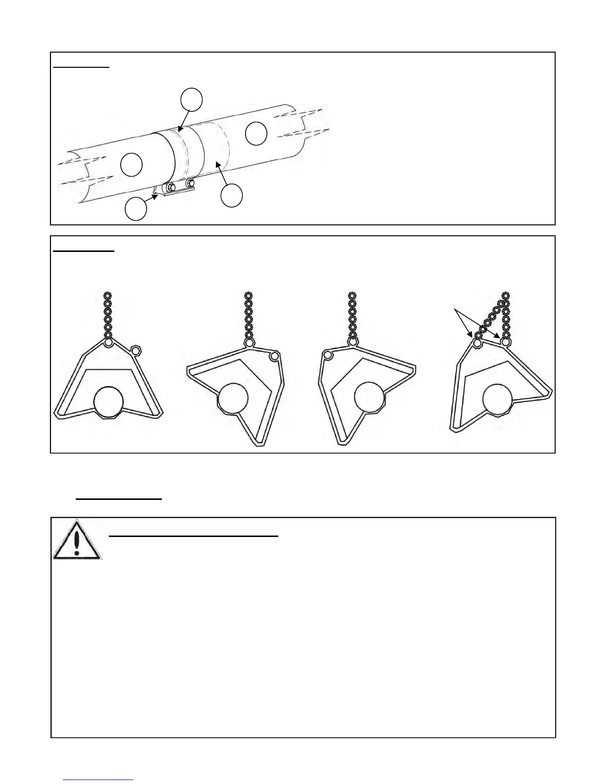
FIGURE 10 HANGER / REFLECTOR ORIENTATION HORIZONTAL TO 45
0
FOR ANGLE LESS
THAN 45° USE
CHAIN TO BOTH
EYES ON
HANGER
45°
45°
 Loading...