39
S100-F / ITB-F I&O Manual
IM101230
RD: JAN 2014
RL: 9A
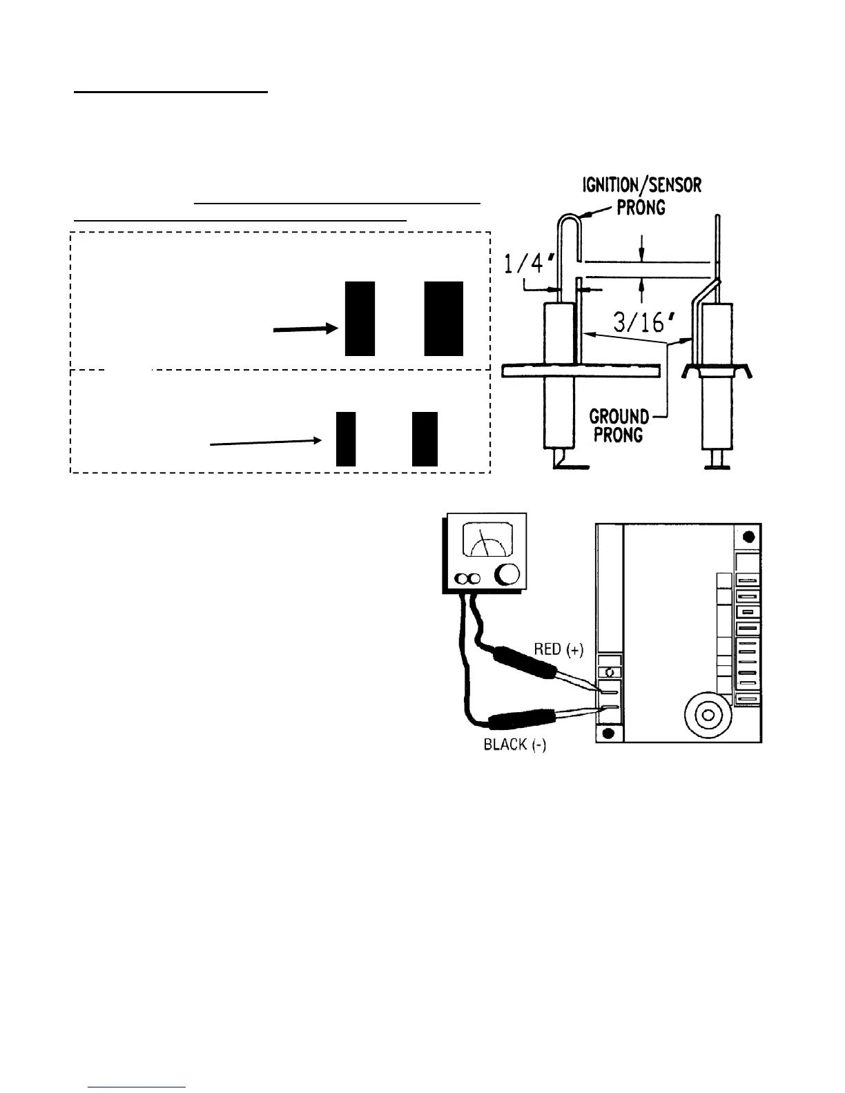
USE THE BLACK BARS BELOW AS A GUIDE FOR AD-
JUSTMENT. USE THE BARS THAT COINCIDE WITH
THE FORMAT & SIZE OF THIS PUBLICATION .
SPARK IGNITER SET UP
Use the following diagram to check the Igniter gap. If the gap is incorrect all adjustments
should be made to the GROUND PRONG/PIN ONLY! DO NOT BEND THE IGNITER
PRONG!!!!
3/16”
1/4”
3/16” 1/4”
IF
this manual is in
8.5” x 11” “booklet” format
(pages folded in half)
then use these bars
IF this manual is printed
8.5” x 11” “full page” format
use these bars
OR
ADJUST
SERVICE CHECKS
Flame current passes through the flame from
the sensor to ground. The minimum flame cur-
rent necessary to keep the system from lock-
out is 0.7 microamps. To measure flame cur-
rent, connect an analog DC microammeter to
the FC- FC+ terminals per figure at right.
Meter should read 0.7 µA or higher. If the me-
ter reads below “0” on scale, meter leads are
reversed. Disconnect power and reconnect
meter leads for proper polarity.
FC- FC+
Use Microamp
scale
Multipurpose Meter
 Loading...