13
S100-F / ITB-F I&O Manual
IM101230
RD: JAN 2014
RL: 9A
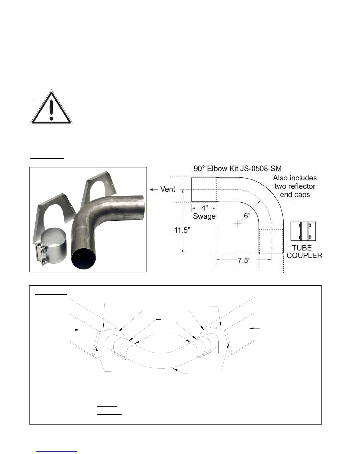
FIGURE 3 SYSTEM ELBOW KIT - see page 50 for 180° elbow dimensions
90° elbows (JS-0528-SM) are shipped as a kit with one coupler, and two reflector end caps.
The S100 / ITB is available in a “U-Tube” model - S100U / ITBU - using a 180° turn box. A
double wide reflector covers the double tube run. Alternately, for a 180° elbow, order 2 x 90°
kits that connect to create a 180°.
IMPORTANT: Models with input 100 Mbh x 20 ft (30 kW x 6 m) must only be installed as a
straight system with no elbows allowed at the 10 ft (3 m) location.
Elbow Location / Input: A minimum run of straight radiant tube must be con-
nected to the burner before any elbow as follows: Inputs 200 (60 kW) and 175
Mbh (50 kW) = 25 ft (7.6 m); Input 155 Mbh (45 kW) = 20 ft (6 m); Inputs 130
Mbh (38 kW) and 110 Mbh (32 Kw) = 15 ft (4.6 m); and Inputs 80 Mbh (23 kW),
60 Mbh (18 kW), and 45 Mbh (13 kW) a minimum of 10 ft (3 m) straight tube be-
fore elbow.
5 90
0
Elbow
6 Tube Coupler
7 Unswaged end of elbow and tube (swage
of previous tube or elbow inserted).
1 End-Cap
2 Reflector
3 End Cap Flange OVER
Reflector
4 End Cap Flange UNDER
Reflector
1
2
2
3 3
4
4
5
6
7
FIGURE 4 90° ELBOW INSTALLATION
 Loading...